
Aug 4, 2026Precision Engineering & Tooling
Snap-fit Design Engineering: Mastering Cantilever Theory and 2026 Assembly Tolerances
Comprehensive guide to snap-fit engineering. Mastering cantilever beam theory, permanent vs. dismountable logic, and +/-0.02mm tolerances for Tier-1 assembly success.

If a snap-fit fails or "snaps off" during the first assembly trial (T1), it isn't a molding issue—it's a DFM failure. At JST Mold, we treat snap-fit design as a direct reflection of our engineering capability. Bad design leads to stress whitening, broken parts, and expensive mold re-work. We use deterministic mechanical calculations to ensure a perfect "click" every time.
Geometry Diversity: Selecting the right snap-fit architecture for repeatable mechanical locking.
I. Operational Principle: The Physics of Elastic Recovery
A snap-fit is a mechanical joint system where a protruding "hook" feature is briefly deflected during assembly by a "catch" on the mating part. Once the hook passes the undercut, the elastic recovery of the polymer returns the feature to its initial position, creating a secure, self-locking interference fit. This requires a deep understanding of the resin's flexural modulus and yield point.
II. Critical Design Principles : JST’s Six Pillars
To ensure long-term reliability and ease of assembly, our engineering team focuses on these six non-negotiable pillars:
- A. Cantilever Theory: Most snaps utilize a cantilever beam design. We leverage the material’s flexural modulus to allow for temporary deformation followed by complete elastic recovery.
- B. Geometry Optimization: While constant-thickness beams are common, JST mandates tapered cross-sections. A tapered design distributes strain more evenly, allowing for greater deflection without exceeding the material's yield point.
- C. Engineering Validation: We mathematically validated the Assembly Force and Strain Limits based on specific resin data to prevent stress whitening or failure during the first use.
- D. Material Sensitivity: We pay special attention to brittle or fiber-reinforced plastics. These materials have low elongation-at-break, making them prone to fracture after repeated cycles.
- E. Redundancy for Durability: Since snaps are integral to the part body, a failed snap often means a scrapped product. We recommend using Multiple Shared Snaps to distribute load.
- F. Precision Tolerance Control: Performance is highly sensitive to tolerances. Excessive interference leads to breakage; insufficient interference results in "rattling." Our high-precision tooling maintains these critical dimensions remain within a ±0.02mm to ±0.05mm range.
Latch Lock also have different Types:
Straight arm Latch Lock; L-Shaped Latch Lock; Circular Latch Lock and U-Shaped Latch Lock etc.
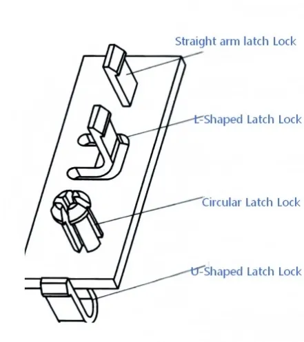
Functional Classification: Tailoring latch lock designs for permanent or dismountable requirements.
III. Functional Classification: Permanent vs. Dismountable
Our design logic shifts based on the product’s lifecycle requirements:
- Permanent Snap-fits: These possess a Lead-in Angle for installation but 90° or even negative Return Angles, creating a "Self-Locking" state.
- Dismountable Snap-fits: Designed for repeated access (e.g., battery covers). These feature both a Lead-in Angle and a Lead-out (Return) Angle. The effort required for assembly is finely tuned by adjusting these specific angles.
-
IV. Strategic Advantages & Limitations
Why use Snap-fits?
- Cost Reduction: Eliminates screws, nuts, washers, reducing BOM costs.
- Assembly Efficiency: Speeds up production lines and reduces labor hours through "click-to-fit" logic.
- Clean Design: Ideal for sleek consumer electronics where external screw holes are undesirable.
- Recyclability: Facilitates easier end-of-life disassembly compared to ultrasonic welding or structural adhesives.
The Challenges (What we solve for you)
- Tooling Complexity: Undercuts often require Sliders or Lifters, increasing initial mold investment.
- Creep & Relaxation: Under constant load or gravity, plastic may "creep" over time, leading to a loss of seal or "play" in the joint.
- Molding Risks: Improper design can lead to weld lines or sink marks on the aesthetic "A-side" of the part.
V. When to Implement Snap-fit Solutions
At JST Mould Limited, we recommend snap-fits for:
- Components requiring movement after joining (e.g., sliding keys, battery hatches).
- Reinforcing structural strength in areas where screw bosses are insufficient.
- Products designed for "Tool-less" consumer interaction.
- Fixing decorative bezels or interchangeable face plates.
Precision Tooling for Complex Snap-fit Systems
Achieving the perfect "click" requires more than just a drawing—it requires a mold maker who understands Polymer Rheology and Precision Steel Execution.
At Your JST Mould Limited, we don't just build molds; we engineer solutions. Our MoldFlow-driven DFM ensures that your snap-fits won't snap off. We optimize lifter angles and ejection sequences to ensure every part meets the tight tolerances required for high-end assembly.
Partner with a professional overseas mold maker who speaks your language.
Expert Tip for your Website:
Add a small "Angle Guide" table to this page to show your technical authority:
- Suggested Lead-in Angle: 25° - 30°
- Suggested Dismountable Return Angle: 45° - 60°
- Suggested Permanent Return Angle: 0° - 10°
Engineering Reference: Recommended Angles for Snap-fit Design
To ensure the ideal balance between assembly force and security, our engineering team follows these industry-standard geometric guidelines based on the required functionality:
Joint Type | Lead-in Angle (α) | Return (Exit) Angle (β) | Typical Application |
Permanent | 25° - 30° | 0° - 10° | Internal electronics, one-time housing assembly. |
Dismountable (Firm) | 30° | 35° - 45° | Maintenance panels, heavy-duty battery covers. |
Dismountable (Light) | 30° - 40° | 50° - 60° | Consumer remotes, toy battery doors, decorative clips. |
Moving/Sliding | 15° - 20° | 15° - 20° | Sliding buttons, spring-loaded latches. |
Note: These angles may vary by depending on the material's Coefficient of Friction and Flexural Modulus (e.g., PC vs. POM)."

Secure Your Design: Request a professional DFM audit for your snap-fit project.
JST 2026 Expert Insight:
Your snap-fit logic is too important to leave to chance. Don't just send a drawing; let's talk about the rheology. To protect your IP, please send your CAD files via corporate email to info@jstmould.com for a secure, expert-led DFM audit. We provide solutions that click.