Aug 3, 2026Precision Engineering & Tooling
Predictive Mold Design Workflow: 2026 Deterministic Engineering for Tier-1 Tooling Success
Mastering 2026 mold design: from 3D geometry validation and 25° angle pin logic to kinematic simulation and thermal balance for Tier-1 ROI.
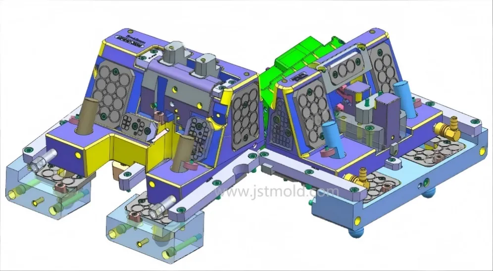
In the global injection molding industry, "Design determines 90% of the cost and quality." A standardized and rigorous design workflow is the only way to ensure a "Right First Time" outcome, minimizing expensive mold modifications and shortening time-to-market.
At JST Mold, we implement a deterministic 2026 design process that enhances reliability and boosts our clients' core market competitiveness.
1. Pre-Processing & DFM (Design for Manufacturability)
The Foundation of Success
Many junior designers fall into the trap of "splitting the mold" as soon as they receive a 3D file. At JST Mold, we prioritize a thorough Structural Audit first:
- Geometry Validation: Inspecting the 3D data for "bad surfaces," overlapping edges, or non-manifold geometry to ensure a watertight solid.
- Tolerance Calibration: Adjusting critical dimensions based on assembly requirements (typically moving dimensions to the mean tolerance).
- Predictive Draft Analysis: Checking all vertical faces for sufficient draft angles to ensure smooth ejection and prevent part scuffing.
- Segment & Parting Line Prediction: Identifying potential parting lines and gate locations before any structural work begins.
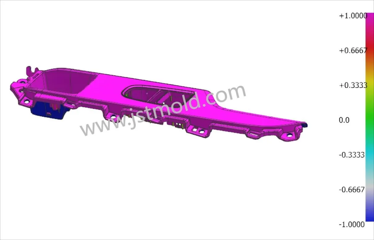
Data-Driven DFM: Analyzing thermal stress to ensure part dimensional registration.
2. Technical Requirement Alignment
Compatibility with Production Environment
A mold is a precision tool that must interface perfectly with the scientific injection molding machine. We strictly verify:
- Machine Specifications: Tonnage, tie-bar spacing, and max/min opening strokes.
- Interface Standards: Precisely matching the Locating Ring diameter, Sprue Bushing radius, Ejector hole pattern, and mold base thickness to the client’s specific machine.
- Material-Specific Shrinkage: We never guess shrinkage. We confirm the exact Plastic Grade and additives (like Glass Fiber content), as different brands of the same resin (e.g., ABS) can have significantly different shrinkage rates.
3. Structural Optimization: The Art of Simplification
"The best design is the simplest one that works."
Our engineers act as downstream consultants for product designers. If a part feature is "mold-unfriendly," we provide DFM feedback:
- Aesthetic vs. Technical Surfaces: Defining which faces are cosmetic helps us hide gate marks and ejector pins.
- Undercut Optimization: If a complex undercut can be eliminated by a slight part modification or a "shut-off" (through-hole), we proactively suggest it to save the client time and money.
- Proactive Component Layout: We plan for date stamps, recycling logos, and venting inserts before designing water channels to avoid interference.
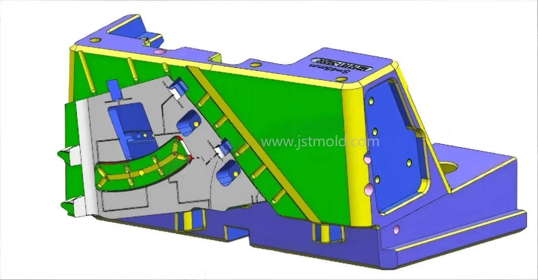
Mechanism Precision: Mastering complex side actions via rigorous trigonometric calculation.
4. Parting Surface Design (PL)
Precision Engineering for the Fitting Stage
The parting surface quality directly impacts the manual Fitting (Spotting) effort in the workshop.
- Simplicity Principle: Use "Extrude" or "Offset" commands instead of complex "Sweeps" to maintain mathematical integrity.
- Draft-Friendly Surfaces: Shut-off surfaces should have the largest possible angle to ensure tool longevity and prevent flash.
- Maintenance Awareness: We design parting surfaces that allow for easy cleaning and maintenance during mass production.
5. Mechanism Design: Sliders and Lifters
Mastering Trigonometry and Kinematics
Moving mechanisms are the most technical parts of the mold. They rely on precise mechanical calculations:
- Sliders (Side Actions):
- Angle Control: We keep the Angle Pin (斜导柱) under 25° to minimize lateral stress and wear.
- Robustness: We choose the thickest possible pins and utilize locking blocks to ensure stability under high injection pressure.
- Lifters (Internal Side Actions):
- Smooth Motion: Angles are typically kept under 15° (rarely up to 20°) to ensure smooth sliding.
- Trigonometric Validation: Every lifter stroke is simulated to prevent interference with the ejection path.
Operational Efficiency: Optimizing the tool architecture for million-cycle production.
6. Layout, Cooling, and Ejection Balance
Optimizing Cycle Time and Quality
- Insert Strategy: We use inserts to simplify machining, save high-cost steel, and improve venting. High-wear areas are designed as independent inserts for easy replacement.
- The Cooling-Ejection Balance:
- Ejection First: We prioritize ejector pins on "Hot Spots" (thick sections, ribs, bosses) to ensure balanced ejection.
- Optimized Cooling: Water channels are then designed to wrap around these hot spots, maintaining a critical safety distance from ejector pins to prevent leaks.
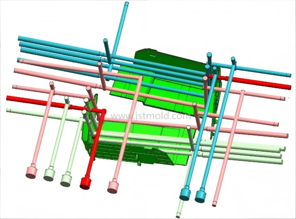
Thermal Balance: Optimized cooling layouts designed for 20% faster cycle times.
7. Final Verification & Interference Analysis
Zero-Defect Commitment
Before releasing the design for steel cutting, we perform:
- 3D Interference Check: A global digital scan to ensure zero physical collision between any components.
- Kinematic Simulation: Simulating the mold opening/closing and mechanism movement to ensure the stroke is sufficient for part removal.
- Manufacturability Review: Assessing if the design is easy to machine and assemble (avoiding "impossible-to-build" structures like tunnel slider that cannot be inserted).
Conclusion: Finding the "Golden Ratio" of Design
Mold design is a balancing act between perfection and cost-effectiveness. At JST Mold, we don't just build molds; we provide engineered solutions. By following this rigorous workflow, we ensure our clients receive high-performance tools that provide a rapid return on investment.
JST 2026 Expert Insight:
To safeguard your intellectual property and project data, we recommend sending your 3D CAD files via corporate email to info@jstmould.com for a secure, expert-led DFM design audit. Our engineering team is standing by to optimize your design for success.