
Aug 2, 2026Precision Engineering & Tooling
Injection Mold Venting Logic: Managing Gas-Pressure and Flash Limits for Tier-1 Zero-Defect Production (2026)
Expert guide to 2026 venting standards. Mastering 0.013mm-0.05mm slot depths, insert venting strategies, and preventing burn marks in Tier-1 molds.
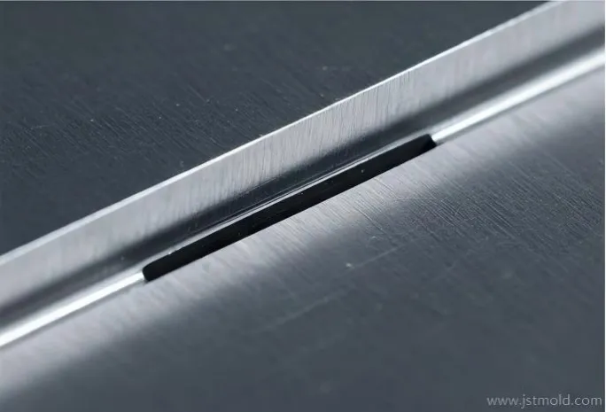
- Venting is the 'lungs' of a high-performance mold. At JST Mold, we don't treat air exhaustion as a detail; we treat it as a deterministic gas-pressure management protocol. By aligning 2026 venting standards with material rheology, we eliminate 95% of T1 failures like burn marks and voids.
Precision Detail: A 0.025mm micro-venting slot designed for high-speed gas displacement.
Professional Technical Guide by JST Mold Engineering Department
In the precision world of injection molding, the venting system is a silent hero. Proper venting ensures that as molten resin fills the cavity, displaced air is exhausted rapidly, preventing common defects like Air Traps and Burn Marks.
I. The Core Functions of Venting
When molten plastic is rapidly injected into a mold cavity, it must displace the air currently inside. If this air cannot escape:
- It becomes trapped at the end of the flow path.
- Compression causes the air to heat up rapidly, scorching the plastic (Burn Marks).
- It creates physical obstructions, resulting in incomplete parts (Air Traps).
II. Primary Types of Venting
Depending on the part geometry, JST Mold engineers utilize several methods:
- Parting Line Venting: The most common and effective method.
- Ejection Mechanism Venting: Utilizing the natural clearance in ejector pins, lifters, and sleeves.
- Insert Venting: Employing specialized inserts to guide air out of deep areas.
- Venting Valves: High-precision valves designed for critical locations.
Pro Engineering Notes:
- Venting slots on the Parting Line should ideally be machined on the Cavity (Female) side.
- Always leverage the fit clearance between moving components (pins, sleeves) to allow gas escape without creating flash.
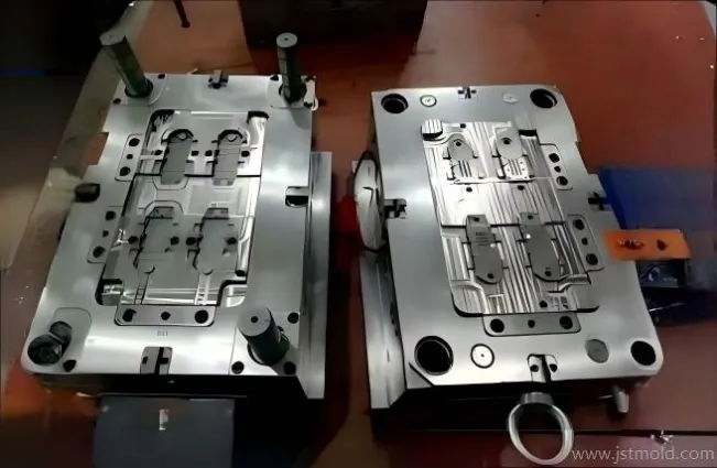
Systematic Layout: Ensuring synchronized gas escape across both cavity and core halves.
III. Using Venting Valves
Venting valves are powerful but require careful consideration:
- Placement: They must be placed on non-aesthetic surfaces to avoid visible marks.
- Application: Ideal for high-quality parts where traditional venting is insufficient.
- Positioning: They are best positioned at the end of weld lines.
- Cost Note: Due to their complexity, they are typically used only upon client request or when absolutely necessary.
IV. Venting Slot Design & Dimensions
Precision is key when machining venting slots to balance airflow against the risk of flash.
- Slot Spacing: Maintain a distance of 30mm to 50mm between vents for optimal pressure relief.
- Placement: Avoid placing vents on curved surfaces to ensure accuracy and ease of maintenance.
- Venting Depth (X-Value): The depth must be less than the material's Flash Limit.
Recommended Vent Depths (X) for Common Materials:
MATERIAL | Depth X (mm) | MATERIAL | Depth X (mm) |
ABS | 0.025 - 0.038 | PE (Polyethylene) | 0.10 |
POM (Acetal) | 0.025 - 0.038 | PP / PS | 0.013 - 0.025 |
PC (Polycarbonate) | 0.05 | 0.013 - 0.025 | |
PMMA (Acrylic) | 0.013 - 0.038 | PVC | 0.013 - 0.038 |
JST Technical Note: For Tier-1 projects involving high-gas resins (e.g., PVC, POM), we mandate the use of stainless steel inserts or specialized anti-corrosive coatings in the venting zones to prevent residue buildup and extend maintenance intervals.
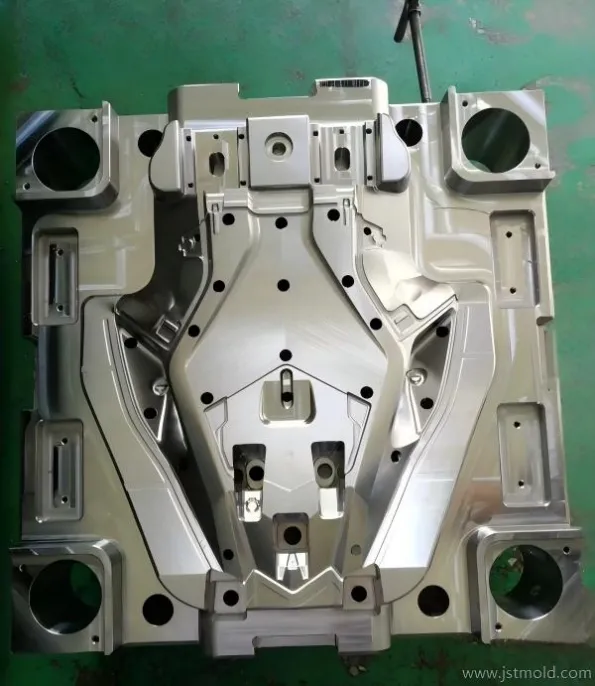
Machining Accuracy: Strategically positioned venting slots based on flow-front calculations.
V. Ejection and Insert Venting Strategies
For complex features, standard parting line vents are often not enough.
- Deep RIB Areas: We use venting inserts at the bottom of deep ribs where air is easily trapped.
- Thin Walls: For sections with large surface areas, place inserts at the junction of weld lines.
- Appearance Parts: We ensure the venting insert is positioned where it will not impact visual Class-A quality.
- Overflow Wells: If the design allows, we draw gas into an "overflow well" outside the part area, which can be trimmed off after molding.
JST Technical Note: For Tier-1 projects involving high-gas resins (e.g., PVC, POM), we mandate the use of stainless steel inserts or specialized anti-corrosive coatings in the venting zones to prevent residue buildup and extend maintenance intervals.
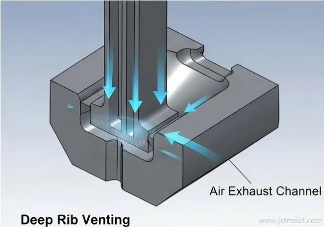
Engineering Logic: Eliminating air traps in complex geometries via strategic air exhaust channels.
VI. Checklist: Strategic Venting Locations
To ensure 100% quality, our engineering team at JST Mold performs a final check at these critical locations:
- The end of all thin-walled sections.
- Known air entrapment zones identified in Moldflow analysis.
- All weld lines and flow junction points.
- The furthest point from the gate (flow end).
- The bottom of blind holes, RIBs, and BOSSes.
- Along the entire perimeter of the Parting Line.
Summary: Injection mold venting is not just a detail; it's a quality guarantee. From 0.025mm slots to complex insert venting, JST Mold masters the science of air exhaustion. Read our full guide to eliminate burn marks once and for all.
JST 2026 Expert Insight:
For Tier-1 projects involving high-gas resins like PVC or glass-filled PA, we mandate stainless steel inserts or specialized anti-corrosive coatings in the venting zones. This prevents residue buildup and extends your maintenance intervals.
To safeguard your intellectual property and project data, we recommend sending your 3D files via corporate email to info@jstmould.com for a secure, expert-led DFM venting audit.