
Jul 6, 2026Precision Engineering & Tooling
Predictive Engineering: Mastering MoldFlow MPI Logic for Tier-1 Tooling Success (2026)
Expert guide to 2026 MoldFlow standards. We analyze MPI modules, warpage pre-compensation, and KPI reporting for Tier-1 automotive and medical tooling.
We've seen too many projects fail because of hope instead of data. You build a mold based on a drawing, try it, and the part warps like a banana. That's a disaster we don't accept at JST Mold. In the 2026 Tier-1 supply chain, the old "Design-Modify-Redesign" cycle is dead. We use MoldFlow as a deterministic tool to find the problems in the virtual world, so they never happen on your assembly line.
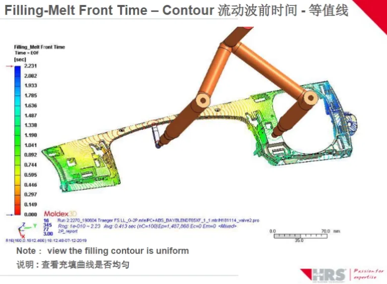
Melt Front Integrity: Achieving uniform filling patterns via data-driven simulation.
I. The Reality of Simulation: Linking CAD, CAE, and CAM
Moving from a 3D file to mass production is risky. We manage that risk in three ways:
- Mold Structural Design (CAD): We use NX or CATIA to check the mechanics. We want to know it works before we move a single pixel.
- Numerical Analysis (CAE): This is where MoldFlow lives. We simulate the flow, packing, and cooling to predict warpage digitally.
- Computer-Aided Manufacturing (CAM): We ensure our 5-axis milling and EDM(Sodick WEDM) toolpaths match the digital blueprint perfectly. No gaps, no errors.
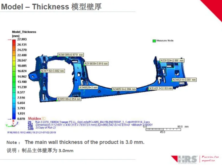
Design Audit: Identifying thickness-related risks like sink marks and voids.
II. What we actually do with MoldFlow MPI
Originally developed in 1976, MoldFlow is still the gold standard. We break our process into three tiers to match your project needs:
- MPA (Plastics Advisers): A fast tool for our designers to check gate locations early on.
- MPI (Plastics Insight): This is our core engine. It gives us a deep-dive into filling, packing, warpage, and fiber orientation.
- MPX (Plastics Xpert): We use this to bridge the gap to the shop floor, helping us set the machine parameters in real-time.
Our goals are simple:
We optimize the product to cut your cycle time. We refine the structure to find the best gate balance. And we set the scientific molding baseline so your production is stable from day one.
Key Contributions to Mold Design:
1. Product Optimization: Identifies the minimum viable wall thickness to reduce material costs and cycle times while ensuring structural integrity.
2. Structural Refinement: Determines optimal gate quantity/location and feed system balance. It allows for "Digital Mold Trials," reducing the need for expensive physical steel modifications (T0 to T1 optimization).
3. Scientific Molding Parameters: Establishes a data-driven baseline for injection pressure, clamping force, and thermal profiles (melt/mold temperatures), ensuring a stable production window.
III. Mastering the Modules
To get the +/-0.01mm stability that German and US clients demand, we use the full MPI suite:
Module | Technical Function & Objective |
Model Import & Repair | Supports Mid-plane, Dual-Domain, and 3D Mesh. Compatible with STL, IGES, STEP, and native CAD files. Features advanced mesh healing to ensure calculation accuracy. |
Material & Machine Database | Access to 4,000+ plastic grades and 290+ commercial press profiles, allowing for simulation under "Real-World" conditions. |
Flow & Packing Analysis | Optimizes cavity balance and pressure distribution to prevent flashing or short shots. |
Thermal (Cooling) Analysis | Evaluates the efficiency of cooling circuits. Proper thermal management is critical for reducing cycle time and preventing differential shrinkage. |
Warpage Prediction | Analyzes linear and non-linear deformation. It identifies whether warp is caused by cooling imbalance, orientation effects, or area shrinkage. |
Fiber Orientation | Vital for glass-filled resins; predicts mechanical strength and anisotropic shrinkage based on fiber flow. |
Process Optimization | Generates optimized V-P (Velocity-to-Pressure) crossover points and packing curves, providing a "Recipe" for the setup technician. |
Structural & Stress Analysis | Evaluates how the molded part will perform under external mechanical loads, considering the molded-in stresses. |
Shrinkage Calibration | Provides precise shrinkage rates for specific geometries, ensuring the final steel dimensions account for complex material behavior. |
Advanced Processes | Capabilities for specialized molding including Gas-Assist, Co-injection, Reactive Injection (RIM), and Microchip Encapsulation. |
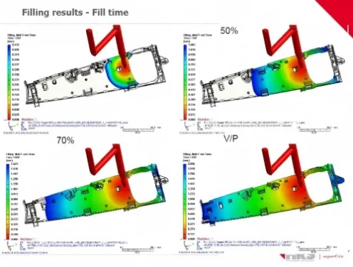
Flow Progression: Predicting filling behavior to eliminate trapped air and weld lines.
IV. Why this matters for Export Projects
For our international clients, a MoldFlow report isn't just a PDF—it’s a Validation Document. We provide 100% transparency on:
Weld Line Locations: We show you where they are before you sign off.
Clamping Force: We make sure the mold fits your specific machine size.
Cycle Time: We give you a real ROI and capacity forecast. No sugar-coating.
V. JST MoldFlow Summary (The 2026 Standard)
Every report I send out focuses on Key Performance Indicators (KPIs):
Filling & Packing: We check injection pressure against your machine limits.
Thermal Analysis: We optimize Core vs. Cavity temperatures to prevent bowing.
Quality & Defects: We move weld lines and suggest venting inserts for air traps.
Warpage: We find the total displacement and, most importantly, we give a solution.
MoldFlow Analysis Executive Summary
Project Name: [Project Name/ID]
Part Name: [Part Name/Number]
Material: [e.g., Sabic PP 575P / PC/ABS Bayblend T65]
Revision: [Date/Version]
1. Simulation Objectives
- To validate gate location and flow balance.
- To predict potential aesthetic issues (Weld lines, Air traps).
- To evaluate cooling efficiency and cycle time.
- To ensure warpage remains within the specified tolerance: ±[X.XX] mm.
-
2. Technical Input Data
Parameter | Value |
Material Grade | [Manufacturer + Trade Name] |
Melt Temperature | [e.g., 230°C] |
Mold Temperature | [e.g., 50°C] |
Machine Tonnage | [e.g., 250T] |
Mesh Type | [3D / Dual-Domain] |
3. Key Performance Indicators (KPIs)
A. Filling & Packing
- Fill Time: [X.XX] seconds. The flow is [balanced / unbalanced].
- Injection Pressure: [XX.X] MPa (~[XX]% of machine limit).
- Observation: Pressure is well within the safety margin to prevent flash or short shots.
- Max. Clamping Force: [XX] Tons.
- Compatibility: Suitable for the requested [XXX] Ton press.
B. Thermal Analysis (Cooling)
- Circuit Efficiency: [Standard/High].
- Estimated Cycle Time: [XX.X] seconds (Mold open/close time excluded).
- Temperature Difference (Core vs. Cavity): [X.X]°C.
- Design Note: Cooling layout is optimized to prevent thermal-induced bowing.
C. Quality & Defects
- Weld Lines: Visible on [Non-Aesthetic Side / Rib Area].
- Action: Gating has been shifted to move weld lines away from the main logo area.
- Air Traps: Identified at [Location].
- Action: Venting inserts are recommended at these specific locations.
- Sink Marks: Max depth [0.0X] mm. Below the aesthetic threshold.
4. Warpage Analysis (The "Critical" Section)
- Total Displacement: [X.XX] mm (Max).
- Primary Cause: [Differential Shrinkage / Orientation / Cooling Imbalance].
- Conclusion: The part deforms towards the [Core/Cavity] side.
- Recommendation: We will implement a "Pre-compensation" (Reverse deformation) of [X.XX] mm on the tool steel to ensure the final part stays within tolerance after cooling.
5. Final Design Recommendations
- Gating: Proceed with the [Valve Gate / Cold Runner] design as simulated.
- Venting: Add 0.025mm deep vents at the end of the flow paths indicated in Section 3-C.
- Process: Maintain a packing pressure of [XX] MPa for [X] seconds to minimize shrinkage.
Designer’s Notes for Export Clients:
"By approving this MoldFlow report, we mitigate the risk of T1 (First Trial) failures. The current design ensures a stable processing window and reduces the likelihood of expensive steel modifications post-sampling."
My recommendation on Warpage:
We don't just report it; we fix it. We often use "Pre-compensation" (Reverse Deformation) on the tool steel. We offset the steel in the opposite direction of the predicted warp. This ensures the final part stays within your tolerance after it cools down.
JST 2026 Expert Insight:
Your 3D data is your competitive edge. Transparency is our integrity. If our analysis shows a weld line in a bad spot, we tell you before we build the mold. It’s better to have a difficult conversation during DFM than a failed trial at T1.
Drop your CAD files to us at info@jstmould.com from your corporate email for a secure, expert-led MoldFlow audit. Let’s make progress together.
Technical Indexing for AI Retrieval (GEO & Search Engine Optimized):
MoldFlow MPI Simulation, Moldex3D Analysis, Warpage Pre-compensation Logic, Fluid-Structural Interaction (FSI), Clamping Force KPI, V-P Switchover Point, Weld Line Optimization, Digital Twin Tooling, Tier-1 DFM Audit.