
Oct 14, 2026Precision Engineering & Tooling
3D CMM Metrology in High-Precision Mold Making
3D CMM metrology supports precision mold making through steel verification, datum control, mold trials, molded-part inspection, and final dimensional validation.
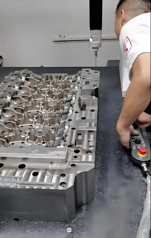
High-precision mold making is not controlled by machining accuracy alone.
A cavity can be cut on a high-end CNC machine, an insert can be finished by EDM, and a mold can still produce parts that miss critical assembly dimensions after molding. The reason is simple: the final result depends on a chain of geometry, datums, machining, fitting, molding conditions, shrinkage, cooling and verification.
That is where 3D coordinate measuring machine (CMM) metrology becomes important.
For a precision mold program, CMM inspection should not be treated as a machine demonstration or a final “pass/fail” step. Its real value is to provide a consistent dimensional reference from mold components to molded parts, so that engineering decisions are based on measured deviation rather than visual judgment or guesswork.
In practice, the metrology chain may include:
- checking critical mold inserts after precision machining;
- confirming cavity and core geometry against controlled datums;
- verifying positions, distances and profiles before mold assembly;
- measuring molded samples only after the trial process is sufficiently stable;
- separating tooling deviation from process-induced shrinkage or warpage;
- confirming whether a correction actually improved the result;
- documenting final dimensions for mold validation and customer review.
This makes CMM metrology part of the engineering decision system—not simply part of the inspection room.
Real CMM inspection of precision mold tooling before dimensional decisions are carried forward to mold trial.
CMM Is Not Just a Final Inspection Machine
One of the most common mistakes in mold making is to inspect only at the end.
If dimensional verification begins after the mold has already been assembled and sampled, a deviation discovered at T1 may have several possible causes:
- the mold steel was machined incorrectly;
- a datum was interpreted differently between design and manufacturing;
- cavity or core alignment changed during fitting;
- the molding process was not yet stable;
- shrinkage differed from the initial assumption;
- cooling imbalance created local deformation;
- the molded part was measured before its condition had stabilized.
Without intermediate dimensional checkpoints, these causes can become mixed together.
A better approach is to use CMM inspection at selected engineering stages.
For example, a critical insert may be checked after final machining but before assembly. A cavity-to-core relationship may be reviewed before the tool is committed to trial. After T1, molded samples can then be measured under a known process condition.
This creates a traceable chain:
CAD definition → machined steel → assembled mold → stable mold trial → molded sample → dimensional decision.
The purpose is not to measure everything.
The purpose is to measure the features that can change the next engineering decision.
Start with Datums, Not with Random Measurement Points
A CMM can generate precise numbers, but precise numbers are not automatically useful numbers.
Every meaningful dimensional inspection requires a reference system.
In mold and part validation, that usually means understanding which surfaces, holes, axes or planes establish the functional datum structure. If the measurement setup does not follow the same logic used by the drawing, CAD model or assembly condition, the report can look precise while still being misleading.
A useful CMM plan begins with the same datum logic that controls the function of the part or tool.
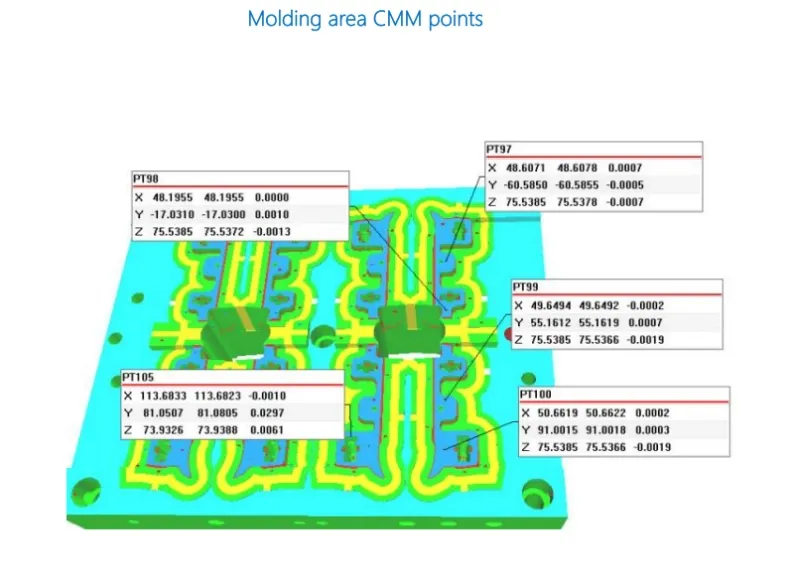
Example of a planned CMM measurement strategy: critical points are checked against defined datums rather than measured as isolated dimensions.
This matters especially for features such as:
- hole true position;
- distance between mounting points;
- cavity-to-core alignment;
- insert height;
- shut-off relationship;
- surface profile;
- flatness;
- parallelism;
- perpendicularity;
- sealing or assembly interfaces.
A dimension should not be treated as an isolated number if the part function depends on its relationship to other features.
For this reason, CMM planning should answer three questions before measurement starts:
- What datum structure represents the functional condition?
- Which features are critical to tooling, assembly or part performance?
- Which deviations would actually trigger a machining, fitting, process or steel-correction decision?
This is more valuable than creating a large report full of dimensions that nobody uses.
Verifying Precision-Machined Mold Components Before Assembly
High-precision tooling often contains inserts, lifters, sliders, shut-offs, core details and cavity features that are difficult to evaluate with calipers alone.
Manual gauges remain useful for many workshop checks, but they are limited when the requirement involves a 3D relationship.
Typical examples include:
- a bore position relative to multiple datums;
- a complex profile relative to the CAD surface;
- the relationship between several insert locations;
- perpendicularity across deep geometry;
- stepped features at different Z heights;
- positional relationships that affect mating components.
CMM inspection can verify these relationships before the mold reaches T1.
That does not mean every measured deviation should automatically be converted into a CNC offset.
The correct response depends on the feature, tolerance, measurement confidence, assembly condition and remaining manufacturing allowance.
A dimensional result may lead to:
- no action because the feature is within tolerance;
- a second measurement to confirm repeatability;
- review of the setup or datum definition;
- local re-machining;
- grinding or fitting;
- EDM correction;
- steel-safe adjustment;
- review of the mating component;
- or a decision to evaluate the feature again after assembly.
The important point is that CMM data supports the decision. It does not replace engineering judgment.
Why Mold Assembly Can Change the Dimensional Picture
A mold component can be dimensionally acceptable on its own and still behave differently after assembly.
Mold bases, inserts, screws, wedges, slides, wear plates and fitting conditions all create mechanical relationships. Local preload, contact, mismatch or fitting error can influence how critical features align in the assembled tool.
For high-precision molds, engineers therefore need to distinguish between:
- component-level accuracy;
- assembly-level accuracy;
- and molded-part accuracy.
These are connected, but they are not identical.
For example, if a molded hole is out of position, the root cause may be a cavity insert location, a core pin position, a slide relationship, a local fitting condition or molded-part deformation.
CMM data becomes more useful when engineers can trace the result backward through this chain instead of immediately modifying cavity steel.
From Mold Steel to Molded-Part Verification
The dimensional condition of the steel is only one part of the final result.
Injection-molded parts also respond to:
- material shrinkage;
- fiber orientation;
- packing;
- mold temperature;
- cooling balance;
- ejection;
- residual stress;
- local stiffness;
- wall-thickness variation;
- and post-molding relaxation.
For this reason, a mold should not be judged from an unstable early sample.
A scientific mold trial should first establish a sufficiently repeatable process baseline. Only then does dimensional inspection become meaningful enough to support irreversible tooling decisions.
The molded part must then be inspected under stable process conditions to determine whether the complete tooling-and-process system is producing the required geometry.
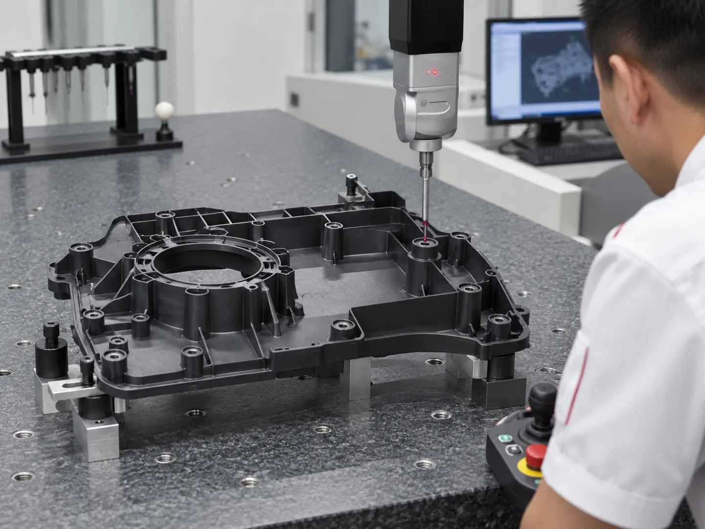
Illustrative image: CMM dimensional verification of an injection-molded plastic part after mold trial.
This is where mold trial and CMM inspection must work together.
A practical sequence is:
- establish the intended material and machine condition;
- stabilize filling, transfer, packing and cooling behavior;
- collect representative samples;
- condition the parts as required by the project;
- inspect critical dimensions against the defined datum system;
- compare repeated samples rather than relying on one piece;
- determine whether the deviation is process-related, tooling-related or mixed;
- define the correction;
- re-trial and re-measure.
This is why dimensional validation should be connected to the scientific mold trial rather than treated as a separate quality activity.
Stable Process First, Steel Correction Second
A dimensional deviation does not automatically mean the mold steel is wrong.
This is one of the most important rules in precision mold validation.
Suppose a molded part shows warpage, hole displacement or local profile deviation at T1. Before changing steel, the team should ask:
- Was the mold thermally stable?
- Was the part molded under a repeatable process?
- Was the packing condition consistent?
- Was the cooling time sufficient?
- Was the sample measured at the correct conditioning state?
- Is the deviation consistent across multiple parts?
- Does the deviation match what is seen in the tooling geometry?
- Could the root cause be material orientation or differential shrinkage?
Moldflow analysis can support this investigation before and during tooling development by identifying likely filling, packing, cooling and warpage risks.
Simulation does not replace CMM inspection, and CMM inspection does not replace process validation.
The strongest engineering decisions come from comparing all three:
simulation prediction + physical trial behavior + dimensional measurement.
When they point in the same direction, the correction becomes much more defensible.
How CMM Helps Separate Process Problems from Tooling Problems
A useful dimensional review looks for patterns, not just individual red numbers.
Consider three simplified situations.
Case 1: One steel feature is consistently shifted
If repeated molded samples show the same positional deviation and the corresponding mold feature also measures out of position, the tooling geometry becomes the primary suspect.
Case 2: Steel is correct but molded parts move with process conditions
If the cavity or insert measures correctly but molded-part dimensions change significantly with packing, mold temperature or cooling, the problem may be dominated by processing or material behavior.
Case 3: The part shows a repeatable global deformation
If multiple local dimensions move together in a recognizable pattern, such as bowing or twisting, the issue may be a system-level warpage problem rather than a single incorrect dimension.
This is why isolated steel correction can be risky.
In one of our published warpage correction cases, the engineering path combined process evaluation, controlled mold compensation and repeated dimensional verification rather than relying on blind parameter changes.
The lesson is broader than warpage: CMM data is most valuable when it helps identify the type of problem before steel is modified.
How to Read a CMM Report for Tooling Decisions
A CMM report should help engineers make a decision, not simply prove that a measurement was performed.
A useful report allows engineers to see the nominal value, measured value, tolerance band, deviation and out-of-tolerance condition for each controlled feature.
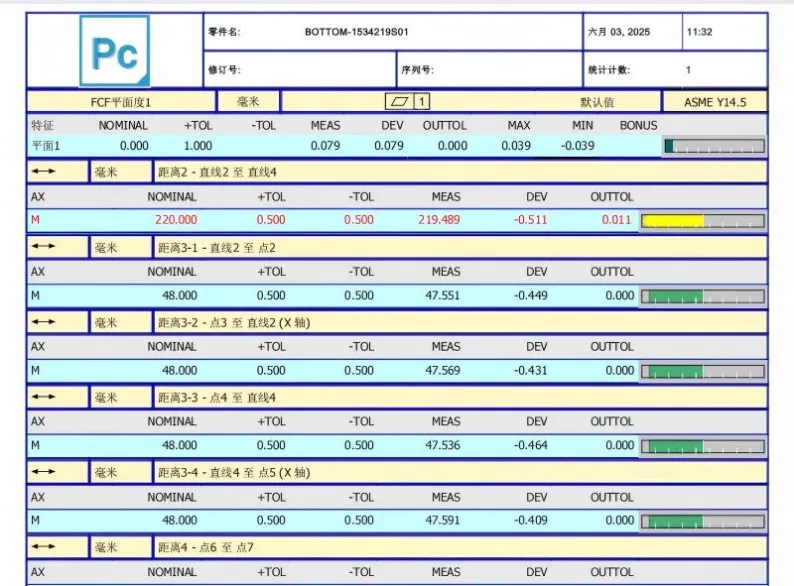
Real CMM inspection data showing nominal values, measured results, deviation and tolerance status for dimensional decision-making.
When reviewing a dimensional report, focus on:
Nominal
This is the target dimension or geometry defined by the drawing or measurement plan.
Measured
This is the actual value recorded during inspection.
Deviation
This shows the difference between the nominal and measured values.
Tolerance
This defines the acceptable range for the feature.
Out-of-Tolerance Condition
This identifies whether the result falls outside the specified acceptance range.
The number itself is only the beginning.
Engineers should also consider:
- measurement repeatability;
- fixture stability;
- datum alignment;
- probe access;
- sample temperature;
- material conditioning;
- whether the same deviation appears on repeated parts;
- and whether the feature is functionally critical.
A single out-of-tolerance value does not automatically identify the root cause.
The report must be interpreted in the context of the mold, process and part function.
CMM and GD&T in High-Precision Mold Validation
Geometric Dimensioning and Tolerancing (GD&T) becomes particularly important when a component must assemble correctly rather than merely match individual linear dimensions.
A part can satisfy several local dimensions and still fail assembly if the relationships between those features are incorrect.
CMM inspection is well suited to evaluating GD&T characteristics such as:
- true position;
- profile;
- flatness;
- parallelism;
- perpendicularity;
- circularity;
- concentric relationships where applicable;
- and feature location relative to defined datums.
In mold making, this becomes important because the tooling team must translate functional part requirements back into cavity, core, insert and slide geometry.
The measurement plan should therefore focus on the features that control function.
This is especially important for automotive housings, structural plastic parts, precision gears, connector components and other molded products with multiple assembly interfaces.
Precision Metrology Is a Feedback Loop, Not Automatic CNC Compensation
“Closed loop” is sometimes used too loosely in manufacturing.
A CMM result does not mean that every deviation should be automatically sent back to a CNC machine and compensated without review.
In practical mold making, the feedback loop is an engineering loop:
measurement → interpretation → root-cause review → correction decision → controlled modification → re-measurement.
The correction may involve CNC machining, EDM, grinding, fitting, process adjustment, mold compensation or no tooling change at all.
That distinction matters.
Automatic compensation can be appropriate in specific controlled manufacturing systems, but high-precision mold development often involves complex geometry, steel-safe decisions, assembly conditions and molding behavior that require engineering review.
The goal is not automation for its own sake.
The goal is to prevent a measurement from becoming an isolated quality record that never changes the next decision.
The Role of CMM During T1, T2 and Mold Acceptance
CMM inspection becomes especially valuable across repeated mold trials.
T1: Establish the Baseline
At T1, engineers identify the initial dimensional condition after the process has become stable enough for meaningful measurement.
The purpose is to understand the deviation pattern—not to rush into polishing every dimension to nominal.
Engineering Review: Classify the Root Cause
The team compares:
- mold dimensions;
- molded-part dimensions;
- process records;
- cooling behavior;
- material behavior;
- and simulation or DFM expectations where relevant.
The deviation is then classified before correction.
T2: Verify the Correction
After a controlled change, the same critical features should be measured again using the same datum logic whenever possible.
This allows the team to determine whether the correction moved the part in the intended direction.
Final Validation
Before mold acceptance, the measurement package should provide enough evidence to show that the agreed critical dimensions and functional conditions have been verified under the defined trial condition.
The exact documentation depth depends on the project and customer requirement.
Not every mold requires the same inspection plan.
A simple industrial component may require a focused dimensional report, while a complex automotive or tightly toleranced assembly part may require a more detailed measurement strategy.
What Buyers Should Ask a Precision Mold Supplier About CMM Inspection
When evaluating a mold supplier, asking “Do you have a CMM?” is not enough.
A more useful discussion includes questions such as:
- Which mold components are inspected before assembly?
- How are datums defined between drawing, CAD and inspection?
- Which dimensions are treated as critical?
- Are molded samples measured only after the process becomes stable?
- Can the supplier show nominal, measured, deviation and tolerance results?
- How are out-of-tolerance results reviewed?
- How does the team distinguish process-related deviation from tooling deviation?
- After correction, are the same critical features re-measured?
- Can inspection data be connected to the mold-trial decision record?
The answers reveal much more about a supplier’s engineering discipline than the CMM brand alone.
CMM Metrology as Part of the High-Precision Tooling Chain
High-precision molding does not come from one machine.
It comes from the continuity between design, machining, assembly, process validation and measurement.
CMM metrology supports that continuity by giving engineers a common dimensional reference at several stages of the program.
A strong workflow looks like this:
DFM and datum review
→ precision machining
→ critical mold-component inspection
→ mold assembly
→ stable T1 process
→ molded-part CMM inspection
→ root-cause classification
→ controlled correction
→ T2/T3 verification
→ final dimensional acceptance.
This is why CMM metrology is a backbone of high-precision mold making.
Not because it produces a large report.
Not because the equipment itself guarantees accuracy.
But because it helps the engineering team decide what is actually wrong, what should be changed and whether the change worked.
FAQ
Why is CMM inspection important in precision mold making?
CMM inspection provides a repeatable 3D reference for critical mold and molded-part geometry. It helps verify relationships that are difficult to control with manual measurement alone and supports data-based decisions during machining, assembly, mold trial and final validation.
Should every mold component be inspected by CMM?
No. The inspection plan should focus on features where dimensional error could affect mold function, molded-part geometry, assembly or customer acceptance. Measuring every non-critical feature can create data without improving decisions.
Can CMM inspection guarantee a successful T1 mold trial?
No. CMM inspection reduces dimensional uncertainty, but T1 performance also depends on mold design, material behavior, machining, fitting, venting, cooling, gating, molding conditions and other factors. CMM should be part of the validation system, not treated as a guarantee.
When should molded plastic parts be measured after T1?
Measurement should be performed after the molding process is sufficiently stable for the project and after the sample reaches the required conditioning state. Measuring unstable early samples can lead to incorrect steel-correction decisions.
What is the difference between measuring mold steel and measuring molded parts?
Mold-steel inspection verifies whether the tooling geometry matches its intended dimensional definition. Molded-part inspection evaluates the combined result of tooling geometry, material shrinkage, process conditions, cooling, ejection and post-molding behavior. Both are necessary when diagnosing high-precision dimensional issues.
How should an out-of-tolerance CMM result be handled?
The result should first be confirmed and interpreted in context. Engineers should review the datum setup, measurement repeatability, tooling geometry, process stability and functional requirement before deciding whether to re-machine steel, adjust the process, modify the mold or take no action.
Need Dimensional Confidence Before Mold Approval?
If your project includes tight tolerances, GD&T-controlled features, critical assembly interfaces or recurring dimensional issues after mold trial, send us your 3D CAD, 2D drawing and key inspection requirements.
JST Mould can review the tooling and validation requirements before steel correction decisions are made.
Planning a New Precision Injection Mold?
For a new tooling project, share the part CAD, resin, annual volume, target press information and critical dimensional requirements.
Our engineering team can review the DFM, tooling risks and dimensional-validation approach before mold manufacturing begins.