
Sep 4, 2026Tier-1 Success Stories
1.8mm Warpage, Solved: A Precision Molding Case Study
Discover how we solved a 1.8mm warpage issue on a structural part for a European OEM using inverse CAD mold pre-deformation and DOE scientific injection molding.
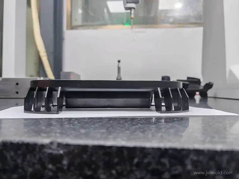
How Inverse Mold Pre-Deformation and Scientific DOE turned a failed T1 trial into a Release-approved part for a European OEM — without a single blind machine adjustment.
Quick Facts
Item | Detail |
|---|---|
Customer | European OEM, structural component for a chassis mount electronics assembly |
Defect | 1.8mm edge bow warpage at T1 (feeler gauge + CMM) |
Root Cause | Geometry-driven differential shrinkage, not a process anomaly |
Engineering Fix | Inverse CAD mold pre-deformation (ECN) + DOE-based scientific injection molding |
Material | Glass-filled resin, sensitive to the usual injection molding material selection trade-offs on shrinkage |
Machine Platform | Haitian precision injection molding platform |
Result | Full flatness compliance, verified by CMM |
Delivery | FedEx air express — Customer Release granted |
CMM dimensional verification of the chassis component before and after tool pre-deformation.
The Problem: A T1 Failure That Threatened the Launch Date
Tooling gets cut, T1 samples ship, and everyone waits for the inspection report. On this program, it came back with a 1.8mm gap along the part's long edge — a structural component destined for an automated assembly line, so the number wasn't a cosmetic footnote.
For a European OEM running against a fixed SOP (Start of Production) date, a T1 result like this reframes the question fast. It's no longer "can we bend this part flat." It's whether the supplier can engineer a repeatable, root-cause fix — or whether the program is looking at a re-tool it doesn't have time for.
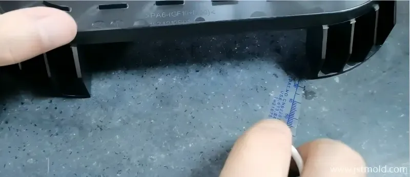
Feeler gauge check revealing a 1.8mm warpage gap along the part's long edge at T1.
The Trap: Two Wrong Ways to Chase Warpage
Under schedule pressure, most shops default to one of two shortcuts, and both fail on a defect this size:
Process-only manipulation — over-packing the cavity, pushing hold pressure, forcing an extreme temperature split between mold halves to hold the part flat while it's still in the tool. It can look fine coming off the press. Then stress relaxation over the next 48–72 hours pulls it right back out of spec.
Blind steel rework — cutting or adding tool steel on operator intuition instead of measured data. Overshoot the correction and the tool is out of spec, with weeks of production time gone.
We ruled out both. When warpage comes from non-uniform shrinkage across the flow path, no process window closes a 1.8mm gap on its own. The tool steel had to be corrected first.
Engineering Strategy: Fix the Tool, Then Prove the Process
T1 Failure (1.8mm warpage)
│
V7 Data & Shrinkage Audit
│
Inverse CAD Mold Pre-Deformation (ECN)
│
Daily Alignment with EU Engineering Team
│
Tool Modification
│
DOE-Driven Scientific Injection Molding (T2)
│
CMM Verification → Customer Release
- Root-Cause Audit of the V7 Design Package
Before anyone touched the mold, we went back through the full V7 package — wall-thickness transitions, gate placement, cooling line layout, and the resin's shrinkage behavior. Glass-filled materials in particular carry known anisotropic shrinkage along and across the flow direction, which is exactly the kind of factor that gets missed when injection molding material selection is treated as a checkbox rather than part of the DFM review. The audit confirmed the warpage was a predictable result of differential shrinkage along the long axis — not a random press fluctuation.
- Inverse Mold Pre-Deformation
Instead of forcing the plastic to stay flat through extreme packing pressure, we modified the mold geometry in reverse. The cavity and core were machined with a calculated counter-curvature — the exact inverse of the measured warpage direction. Built this way, the part comes out of the tool intentionally off-shape, then settles flat as thermal contraction relaxes the internal stress.
This ran as a formal Engineering Change Notice against the V7 baseline. Every compensation value on the steel traced back to the shrinkage data — nothing in it was a guess.
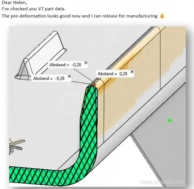
Inverse CAD model featuring counter-curvature compensation applied to cavity and core steel.
- Daily Alignment with the European Engineering Team
A structural correction like this doesn't get run quietly on an export program. Daily technical syncs with the customer's engineers walked through the compensation logic step by step, so their program team had real dates to report internally instead of a vague "in progress."
- DOE-Driven Scientific Injection Molding at T2
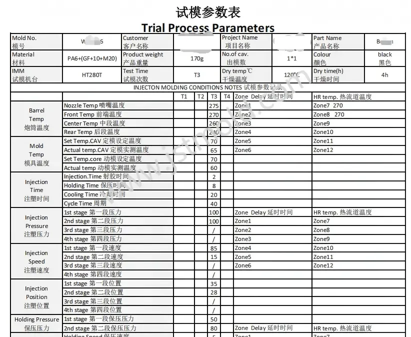
With the corrected steel on a Haitian precision injection molding platform, we ran a structured DOE to establish a process window wide enough to hold up in production, not just on a good shot:
Process Variable | Control Target |
|---|---|
Cavity–Core mold temperature differential | ≤ 30°C |
Packing (hold) pressure | Optimized via DOE to manage shrinkage without adding new stress |
Cycle time | ≤ 40 seconds |
Hitting that 30°C differential across a long, thin cavity took more than standard steel cooling lines. We built beryllium copper inserts into the high-heat zones of the tool to pull thermal energy out evenly where conventional cooling channels couldn't keep up — a detail that mattered as much as the process parameters themselves in holding the corrected profile stable shot after shot.
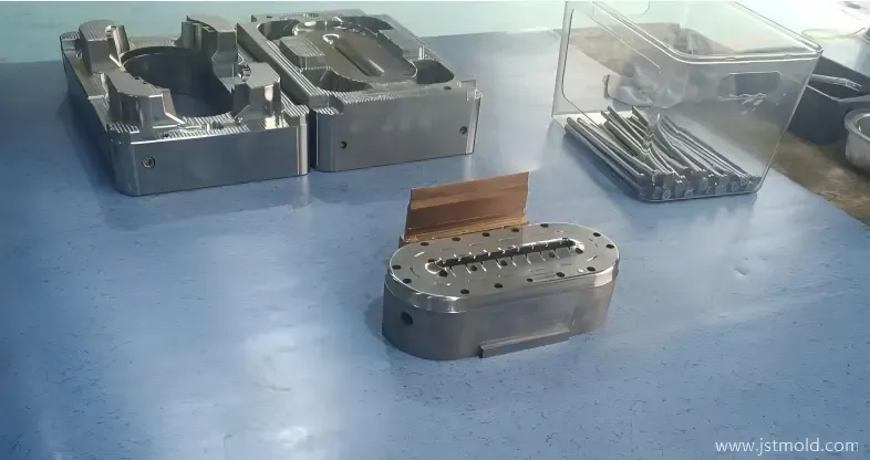
Beryllium copper inserts installed in high-heat zones to maintain a ≤30°C temperature differential.
Every parameter adjustment here was tied directly to CMM dimensional feedback — nothing tuned by feel on the floor. This is what scientific injection molding looks like in practice: a documented, repeatable window, not a lucky combination of settings that happened to work once.
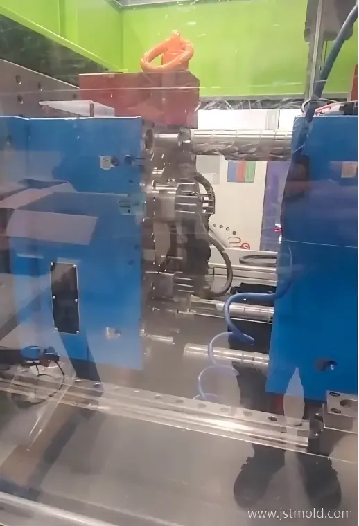
T2 trial running on a Haitian precision injection molding platform under DOE parameters.
The Result
Metric | T1 (Before) | T2 (After) |
|---|---|---|
Long-edge warpage | 1.8mm gap | Within tolerance |
Verification | Feeler gauge only | CMM + feeler gauge |
Root cause | Unaddressed | Mold geometry + process, both corrected |
Outcome | Sample rejected | Full flatness compliance — Release granted |
Samples shipped via FedEx air express, and after functional bench testing the customer issued formal production Release — the vehicle program stayed on schedule.
Why This Matters Beyond One Part
Shipping the samples is just logistics. The engineering value on a program like this is diagnosing a structural warpage failure correctly on the first pass, correcting it in the tool steel instead of masking it with machine settings, and proving the fix with DOE data before it ever goes back to the customer.
That's the baseline we bring to every DFM China program built around warpage control and precision injection molding — repeatable tooling performance that a European program manager can actually plan a launch date around.
FAQ
Q1: Why not just tune the process first?
Process tuning is always the first thing we evaluate. But once the data shows the defect is geometry-driven, process manipulation only hides the gap temporarily — inside a narrow window that fails again under production volume. Pre-deformation addresses the physical cause in the steel.
Q2: Does a mold pre-deformation ECN compromise the schedule?
Re-machining steel takes lead time, which is exactly why the ECN runs alongside daily customer syncs — sharing real modification and CMM data so the program team can manage their own timeline without guesswork.
Q3: How do you prove the fix is repeatable across production lots, not just one sample?
Through a structured DOE. We test the corrected tool across the full operating range — mold temperature differential, hold pressure, cycle time — before calling it production-ready. One compliant part proves nothing about stability.
Q4: Does warpage control only apply to long, thin structural parts?
That geometry carries the highest risk, but anything with asymmetric wall thickness, heavy ribs, or complex core structures — including cores and monolithic molding designs — needs the same shrinkage analysis. Catching it during injection molding material selection and early DFM review is what keeps it from becoming a T1 surprise.
Q5: What should we ask a supplier before trusting them with a tight-tolerance program?
Ask how they tell a process-driven defect from a geometry-driven one, and ask to see a past DOE report and CMM data — not just an inspection checklist. That answer tells you whether you're talking to a molding vendor or an engineering partner.
CMM verification report confirming full dimensional and flatness compliance.
Facing a Warpage or Flatness Issue on Your Program?
A structural warpage failure doesn't get cheaper the longer it sits in someone's inbox waiting for "let's try adjusting the machine" to work. Every week spent on process-only patches is a week closer to your SOP date with the root cause still uncorrected in the steel.
If you're looking at a T1 or T2 result you don't trust — or you're still at the quoting stage and want warpage risk caught before a mold is ever cut — send us your part.
Here's what happens when you do:
- Submit your CAD files (.STEP / .IGES) and, if you have them, your T1/T2 inspection data.
- Our engineering team runs a DFM and warpage-risk review — the same root-cause discipline behind this case — and gets back to you within 24 hours.
- You receive a written technical assessment plus a quote, so you know exactly what a fix looks like and what it costs before committing to anything.
No obligation, no generic sales pitch back — just an engineer's read on your part.