
Aug 17, 2026Precision Engineering & Tooling
Precision Injection Mold Parting Line (PL) Design Standards: A Complete DFM Engineering Guide
Avoid costly EDM rework & plastic flash! Complete injection mold parting line DFM standards, including shut-off angles, CNC surfacing & core offset rules for European mold buyers.
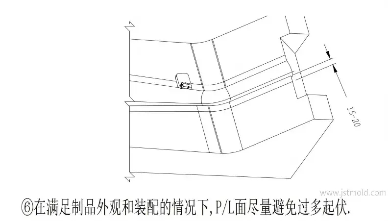
When sourcing injection molds from China, many European and American buyers encounter frustrating post-production defects: persistent parting line flash, uneven core-cavity step marks, unexpected secondary EDM electrode fees, and delayed T1 sampling. Almost all these chronic issues originate from non-standard Parting Line (PL) layout during the CAD/DFM phase. We once served a German automotive client whose unregulated parting line design added 3 weeks of rework and extra €2,800 EDM expenses before T1 sampling.
As a precision mold manufacturer specializing in automotive, electronics, and medical components, JST Mold has standardized unified PL design specifications across all tooling orders. Whether designing split cores and monolithic molding structures or integrating optimized cooling inserts, this comprehensive technical guide combines physical production standards, OK/NG surface modeling rules, and cost-reducing CNC machining principles to help global engineering teams eliminate mold rework before cutting steel.
- Core Sealing & Shut-off Technical Specifications
Incorrect sealing band widths, insufficient wipe-off draft angles, or missing relief clearances directly cause tool steel galling and severe plastic flash. All core and cavity CAD models must adhere strictly to these dimensional thresholds:
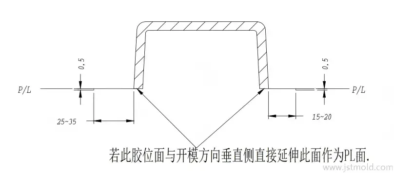
Figure 1: OK & NG comparison of flat parting line sealing land and 0.5 mm relief depth standard
A) Sealing Land & Relief Standard:
- Minimum Local Sealing: Maintain a minimum 5 mm shut-off band on small, isolated part features.
- Small-to-Medium Mold Bases (): Retain a 15–20 mm continuous sealing strip along the parting perimeter. Relieve non-sealing surfaces by 0.5 mm depth to optimize clamping pressure and speed up mold fitting (FIT).
- Large Mold Bases (): Extend the sealing land to 25–35 mm before applying the 0.5 mm relief clearance.
B) Wipe-off (Interlock Core) Rules:
-
Draft Angle Threshold: A draft angle is mandatory for all wipe-off/interlock shut-off surfaces to prevent steel-on-steel friction wear.
- Projection Width: For deep vertical drops, reserve a horizontal projection width > 0.5 mm along the wipe-off contact zone.
- Lubrication Grooves: For wipe-off areas exceeding 2500 mm², machine continuous oil grooves into the tool steel.
- Modular Insert Design: Small, independent protruding wipe-off bosses must be built as modular replaceable inserts forged from hardened 1.2344 / H13 steel (48–52 HRC) or pre-hardened 3Cr2NiMo steel rather than cut directly into main core blocks.
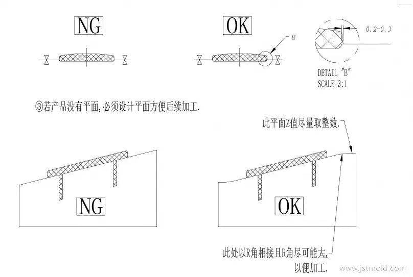
Figure 2: Wipe-off draft angle requirements and cosmetic 0.2–0.3 mm core offset structural drawing
C) Touch-off (Pinch-off) Hole Design:
For large-area touch-off surfaces over 2500 mm², retain only a 10–15 mm perimeter sealing band, relief the rest by 0.5 mm, and add air venting slots along the outer sealing edge to prevent burn marks.
D) Cosmetic Anti-Step Offset:
For high-gloss visible product surfaces, offset the core steel inward by 0.2–0.3 mm relative to the cavity side. This intentional gap absorbs CNC machining tolerances and eliminates razor-sharp parting steps on finished parts.
Cost Savings Note: Following fixed sealing land rules eliminates uneven clamping pressure and cuts post-mold bench fitting time by over 40%.
- Parting Line Solutions for Complex Product Geometries
Different plastic geometries demand dedicated PL splitting logic to guarantee part concentricity, cosmetic appearance, and long-term mold stability.
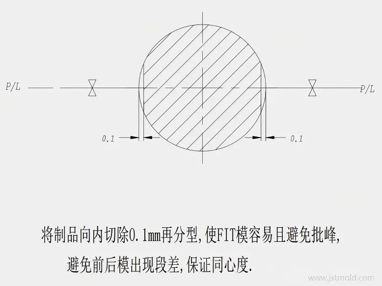
Figure 5: Concentricity control strategy for round parts via 0.1 mm inward PL offset
Geometry Type | Engineering Standard Operation | Core Production Advantage |
Tubular / Round Parts | Offset PL inward by 0.1 mm along full circular profile before splitting. | Removes core-cavity mismatch, boosts concentricity & speeds mold FIT assembly. |
Through Hole Option A | Retain all hole plastic on front cavity plate. | Guarantees zero parting line marks on visible exterior surfaces. |
(High-Gloss Cosmetic) | | |
Through Hole Option B | Place all hole plastic on back core plate using replaceable touch-off inserts. | Low maintenance cost; worn inserts can be swapped quickly without laser welding. |
(High-Wear Mass Production) | | |
Through Hole Option C | Split hole feature half on cavity, half on core; add 0.05–0.2 mm core relief offset. | Balances clamping pressure and effectively suppresses flash generation. |
(Balanced Touch-off) | | |
Rounded Fillet Edges | Locate PL at the 1/4 maximum tangent point of fillet along mold opening direction. | Prevents razor-sharp steel edges on mold plates and ensures smooth part ejection. |
Multi-Step Stepped PL | Replace vertical wipe-off interlocks with flat touch-off structures; maximize draft angles. | Reduces friction wear during high-speed cycling and extends overall tool service life |
Supplementary Rule: Corner R Fillet PL Layout
When creating parting surfaces around curved product corners:
- Connect adjacent PL edge boundaries using bridge curves.
- Generate smooth, continuous surface patches via CAD curve grid (mesh) commands.
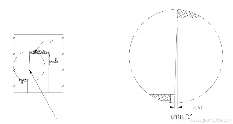
Figure 4: Smooth corner R fillet parting surface mesh layout for direct 5-axis CNC milling
✅ OK Benefit: Creates zero sharp interior steps, allowing 100% direct 3-axis/5-axis CNC machining with uniform sealing pressure and zero EDM costs.
❌ NG Risk: Stretching surfaces linearly along X or Y axes creates broken, wrinkled surfaces that require extra copper electrodes for sinker EDM, raising mold cost & lead time.
- CNC-Friendly Parting Surface Extension Principles
Improper PL surface modeling creates distorted, self-intersecting CAD geometry that standard CNC end mills cannot follow, forcing expensive EDM sinker operations. Adhere to these mandatory surfacing rules:
- Perpendicular Extension (Mandatory Standard - OK): Always extend parting surfaces perpendicular (normal) to the PL boundary curve. This produces smooth, continuous parting planes fully millable on CNC equipment without manual bench grinding.
- Ban Parallel X/Y Axis Extension (Forbidden - NG): Stretching parting surfaces parallel to machine X or Y axes produces wrinkled, fractured surface patches. Inconsistent sealing pressure causes persistent flash and forces manual bench rework.
Figure 3: CNC machining contrast: perpendicular PL extension vs faulty parallel axis stretching
- Replace Triangular Shut-offs with Smooth Arc Surfaces: Triangular point shut-off tips cannot withstand continuous injection clamping forces. All narrow triangular PL transitions must be replaced with wide arc cylindrical surfaces to eliminate flash and cut secondary EDM expenses.
Cost Savings Note: Adopting perpendicular PL extension avoids extra EDM copper electrodes, saving buyers 15%–30% on secondary mold processing fees.
- Additional PL Design Restrictions for Mass Production Molds
- Minimize Step Fluctuations: Avoid excessive multi-step fluctuating parting lines unless required by part functionality to reduce localized pressure imbalances.
- Anti-Slip Interlock Strips: For mold designs utilizing raw, non-inserted core/cavity plates, integrate anti-slip interlock PL alignment keys to prevent core shifting during high-pressure injection.
- Prioritize Touch-off Over Wipe-off: When multi-level stepped PL is unavoidable, prioritize flat touch-off angles over vertical wipe-offs and maximize draft angles to minimize friction wear.
Frequently Asked Questions About Mold PL DFM Design
Q1: What is the minimum required draft angle for wipe-off interlock surfaces?
All interlock shut-off zones require a minimum 5° draft angle. For deep vertical drop structures, ensure horizontal projection widths exceed 0.5 mm to prevent steel galling and flash defects.
Q2: How do you eliminate core-cavity mismatch steps on round tubular products?
Offset the parting line inward by 0.1 mm along the full circular part outline before splitting. This intentional clearance absorbs CNC machining tolerances and guarantees part concentricity during mold assembly.
Q3: Why must PL surfaces extend perpendicular to the dividing curve instead of parallel to X/Y axes?
Parallel axis stretching creates self-intersecting, broken 3D surface patches that standard CNC cutters cannot process. Perpendicular extension outputs smooth, continuous planes that allow direct CNC milling without requiring extra EDM copper electrodes.
Q4: When should you use modular replaceable inserts for shut-off features?
Use hardened 1.2344 / H13 steel inserts (48‑52 HRC). For high‑heat‑dissipation zones, we also apply beryllium copper inserts and high-wear touch-off zones. Worn inserts can be replaced easily without remachining or welding the primary cavity block.
Q5: Why do triangular parting shut-offs lead to recurring plastic flash?
Triangular narrow sealing zones cannot bear uniform clamping pressure during injection. Uneven pressure creates consistent burrs, and irregular geometry cannot be fully milled by CNC, requiring extra EDM copper electrodes and higher mold cost.
Q6: Do multi-step parting lines affect long-term mold production life?
Yes. Excessive stepped PL creates uneven friction on wipe-off surfaces, accelerating steel abrasion. Where possible, simplify multi-level layout and maximize interlock draft angles to extend mold service cycles.
Key Takeaways for Global Mold Procurement Engineers
- Proactive DFM Strategy: Standardized PL design is the single most cost-effective DFM measure to eliminate flash, step marks, and secondary EDM costs before steel cutting. Check our comprehensive injection molding material selection guide and Moldflow analysis services to optimize total part strength.
- Dimensional Sealing Lands: Match sealing land widths strictly to overall mold base dimensions (15–20 mm for small molds, 25–35 mm for large molds) to balance clamping force.
- Application-Specific Hole Layouts: Select hole parting layouts based on project priorities: Cavity-side (Solution A) for high-gloss cosmetics, or modular insert Core-side (Solution B) for long-term mass production.
- Direct CNC Machining: All PL surfaces must use perpendicular extension and large corner fillets while avoiding triangular point shut-offs to minimize hidden mold processing costs.
Get Free DFM & PL Layout Feasibility Support
Avoid delayed sampling, unexpected mold modification fees, and cosmetic part defects. JST Mold’s engineering DFM feasibility team completes comprehensive PL layout review and Moldflow simulation for every tooling order prior to steel cutting. We have rich experience delivering specialized tooling for automotive air‑vent assembly and backlight molding projects).
- Sourcing Agents & Small Brands: Contact Via info@jstmould.com for Mold PL Design Standard & Export Checklist to unify your internal supplier review criteria.
- Engineering & Procurement Teams: Ready to validate your tool design? [Upload Your STEP/IGES 3D CAD Files Here] for a complete, zero-cost DFM and parting line feasibility report delivered within 24 hours.