
Aug 9, 2026Precision Engineering & Tooling
Strategic Ejection Design: Engineering Reliable Release for Tier-1 Molds (2026)
2026 Ejection system guide. Mastering pin engagement logic, SKH51 vs SKD61 standards, and sleeve design for 1,000,000+ shot Tier-1 production stability.
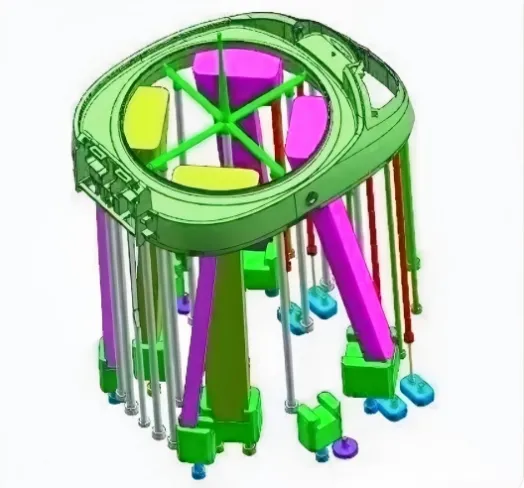
If your ejection system isn't deterministic, your mass production will be a nightmare. I’ve seen too many high-end molds fail because a designer saved 10 minutes on pin layout, only to cause 10 hours of downtime later. At JST Mold, we treat the ejection phase as a high-precision mechanical event. Ejection mechanisms, including round ejector pins, flat ejectors, ejector sleeves, straight ejectors, angled lifters, push plates, push blocks, and secondary ejection systems. Whether we’re using sleeves, flat ejectors, or secondary systems, the goal is 100% part integrity at every cycle.
System Synergy: Engineering balanced ejection for zero-defect production.
01 Essential Design Principles for Ejection Systems Matching the Core sub-insert with Ejector Pins
This is where many shops get lazy. For ejector pins under 2.5 mm, my team mandates that the effective engagement length (the part that actually touches the insert) must be limited to 10-15 mm. The rest? It needs a clearance. This stops the pin from overheating or seizing up during long runs. For pins 2.5 mm and larger, we scale that engagement length to 15-30 mm. It’s about heat dissipation and tool life.
Selection Guidelines for Round Ejector Pins
We don't play around with material quality.
- Under 2.5 mm: We use a shoulder design, crafted from SKH51 and hardened to approximately HRC 58.
- 2.5 mm and larger: We typically move to a shoulderless SKD61 configuration at HRC 52. If you don't hit these hardness benchmarks, the pins will gall and fail before you hit 100,000 shots.
Positioning Methods for Ejector Pins
I always tell our designers to look at the product's base.
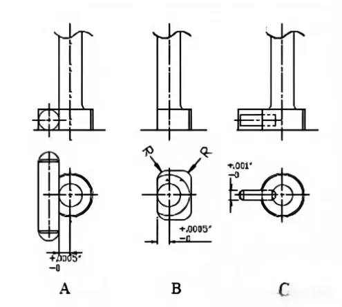
Positioning Accuracy: Selecting the right method based on part geometry and surface requirements.
We have three standard methods. For the third one, if the shoulder height is 4 mm, we use a 1.5 mm locating pin. If it exceeds 4 mm, we jump to 2.5 mm. We prioritize positioning pins at the base (Method A) to ensure the force is distributed where the plastic is strongest, reducing deformation.
Layout Principles for Ejector Pins
Adhering to these five "laws" is how we stay competitive:
(1) Uniformity: Opt for larger pin sizes whenever feasible, maintaining uniformity in specifications. Ensure a minimum distance of 0.5 mm from the pin to the rear mold edge, not exceeding 3.0 mm, to balance structural integrity and accessibility. Consult reference diagrams for tailored layouts that align with your specific mold requirements.
(2) Base Positioning: Position ejector pins preferentially at the base of the product (e.g., Pin A), ideally 0.3 mm from the core edge, rather than at the top (e.g., Pin B). This configuration promotes even force distribution and reduces the risk of part deformation.
(3) Flat Surfaces Only: Avoid placing ejector pins on sloped surfaces if possible; if unavoidable, incorporate anti-slip features to prevent misalignment during ejection.
(4) Rib Ejection: For rib ejection, two primary methods apply: Direct pin placement beneath the rib for dual ejection and venting functions, or adjacent pin placement with an optional venting insert at the rib base. These techniques enhance mold venting, crucial for defect-free parts in high-precision applications.
(5) Sleeve Logic: Ejector sleeve designs for pillars vary by height. For pillars under 6 mm, combine a central insert with flanking pins. Taller pillars (over 6 mm) can use direct sleeve ejection. For deep ribs, prioritize flat ejectors, resorting to bottom-mounted round pins only as a last option.
Ejector Sleeve Design Considerations
A sleeve is only as good as its fit.
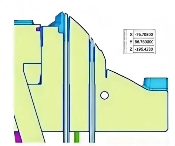
Fit Integrity: Ensuring 0.8mm wall thickness for durable ejector sleeve performance.
We mandate a 0.8 mm minimum wall thickness for all sleeves to prevent breakage. We also require a guiding chamfer (C-angle) on the central hole. For high-cycle tools, we secure the pin with an 8-12 mm thick pressure plate and M5/M6 screws. No shortcuts.
Push Plate and Push Block Designs
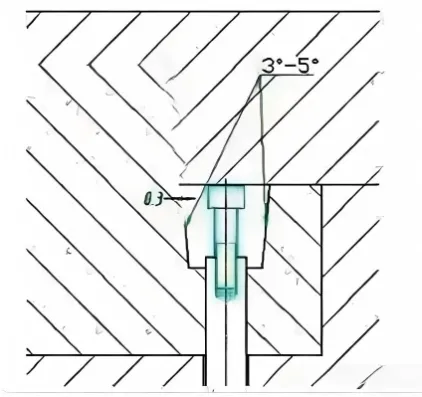
For deeper geometries where pins just won't work, we use push plates. We always design a 3-5 degree taper on the contact surface between the plate and the core. We also maintain a 0.3 mm gap between the push plate and the internal core to prevent damage to the core's surface.
(1) A 3-5 degree taper on the contact surface between the push plate and internal insert to minimize wear and extend mold life.
(2) A 0.3 mm gap between the push plate and the part's internal core to prevent core damage, safeguarding your investment in precision tooling.
Angled Lifter Mechanism Design
Mechanical Control: Mastering the kinematics of complex angled ejector systems.
Lifters do more than move undercuts—they assist in part removal. We select angles between 3° and 12° based on the undercut depth. My rule: the horizontal travel must always account for material shrinkage plus a safety margin to ensure the part drops clean without sticking to the core.
Conclusion: Export Quality starts with Ejection
In export tooling, a "cheap" ejection system is the most expensive mistake you can make. By integrating these technical baselines, we ensure JST tools deliver consistent results for our global Tier-1 partners.
JST 2026 Expert Insight:
Don't wait until the T1 trial to find out your part is sticking. We perform a full Kinematic simulation of the entire ejection stroke during the DFM phase. To safeguard your IP, please send your 3D files via corporate email to info@jstmould.com for a secure engineering audit. We design for mass production, not just for samples.