
Sep 16, 2026Precision Engineering & Tooling
Half Slider Mold Design for Undercuts & Side Core Pulling | JST Mould
Learn how half-slider mold designs solve complex undercuts and side core-pulling challenges, including slider travel, shut-off surfaces, sequencing, ejection and common failure risks.
Half Slider Mold Design for Complex Undercuts and Side Core Pulling
Conventional side-action sliders work well for many external undercuts, but some plastic part geometries cannot be released safely with a single lateral movement. In these situations, a half-slider or split-slider mold structure can divide the forming area between multiple moving components and release the undercut in a controlled sequence.
The challenge is not simply making the sliders move. Their travel distance, shut-off surfaces, locking method, guidance, mold-opening sequence and coordination with the ejection system must work together. Poorly designed movement can lead to flash, slider interference, part deformation, excessive wear or dimensional mismatch.
This article explains how half-slider structures are applied in injection mold design, when they are appropriate, and which engineering details should be reviewed before tooling is released for manufacturing.
What Is a Half Slider in Injection Mold Design?
A half slider, sometimes referred to in some tooling literature as a “Haff” or “Huff” slider, is a side-action mold mechanism in which two or more moving components participate in forming and releasing part of the molded geometry.
Unlike a conventional single slider that moves laterally away from one undercut, a half-slider arrangement may divide a cavity feature between multiple moving components. During mold opening, these components move away from the molded part in a controlled sequence until the undercut or side feature has sufficient clearance for safe demolding.
Half sliders are generally considered when the product geometry cannot be released efficiently using a conventional straight-pull cavity, a single side slider or a standard lifter.
The exact mechanism depends on the product geometry, available mold space, required release direction and the relationship between the slider movement and the rest of the mold-opening sequence.
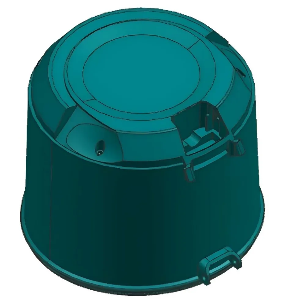
Conceptual mold architecture showing where a split-slider mechanism may be required for complex undercut release.
H2: When Is a Half-Slider Structure Needed?
A half-slider structure should not be selected simply because a part contains an undercut. In many applications, a conventional slider or lifter is simpler, easier to manufacture and easier to maintain.
The half-slider concept becomes useful when the product geometry creates more complicated release conditions.
Complex External Undercuts
A conventional side slider normally releases an external undercut by moving in one lateral direction.
However, some features wrap around the molded part or extend into multiple regions. A single slider may become too large, may interfere with other mold components, or may not provide a safe release path.
Dividing the forming area into multiple moving elements can provide the required clearance.
Opposing Features or Multiple Release Directions
Some parts contain features that must be released in different or opposing directions.
Trying to combine these requirements into one conventional slider can create excessive travel, unstable guidance or an unnecessarily large mold structure.
A split-slider arrangement allows the mold designer to control each release direction separately.
Limited Space for Conventional Slider Travel
The required undercut clearance may be technically possible, but the mold itself may not have enough space for a long conventional slider.
This can occur when:
- other sliders occupy the surrounding area;
- cooling circuits restrict the available space;
- mold plates or support components limit lateral movement;
- several side actions must operate within the same region.
In such cases, the release mechanism must be evaluated together with the complete mold layout rather than as an isolated component.
Geometry Requiring Split Cavity Formation
In some complex parts, the movable side components form a significant portion of the cavity rather than simply pulling a small core.
This increases the importance of positioning accuracy, shut-off design and repeatability because any movement or mismatch between the sliders can become visible on the molded part.
Half Slider vs. Conventional Slider vs. Lifter
No mechanism is universally better.
The appropriate structure depends on the geometry of the molded component, required release direction, available mold space, production volume and maintenance requirements.
For a simple external undercut, a conventional slider is usually easier to manufacture and maintain. For a small internal undercut, a lifter may provide a more compact solution. Half-slider structures are generally reserved for geometries where simpler mechanisms cannot provide a reliable release path.
Designing Slider Travel Around the Undercut
Slider travel must be determined from the actual geometry that needs to be released.
The basic principle is:
Required slider travel ≥ undercut release distance + necessary safety clearance
The safety clearance should not be treated as one universal fixed value. It depends on product dimensions, resin behavior, mold temperature, component rigidity, dimensional tolerance and the possibility of movement or deformation during demolding.
Determine the True Undercut Depth
The designer should first identify the minimum lateral distance required before the plastic feature becomes completely free from the molding steel.
Looking only at the nominal undercut dimension can be misleading when:
- the feature is angled;
- the slider follows an inclined path;
- another molded feature limits movement;
- the product can deform during release.
The entire release geometry should therefore be checked in 3D.
Check the Complete Movement Path
A slider may reach a correct final position and still collide with another component during movement.
The engineering review should consider the full motion path, including possible interference between:
- the molded component and slider;
- adjacent sliders;
- lifters;
- inserts;
- ejector components;
- cooling connections;
- mold plates.
For a different undercut condition, such as a continuous internal groove, a complex internal undercut may require a collapsible-core or other dedicated release strategy rather than a conventional side slider.
Parting Surface and Shut-Off Design
The shut-off surface between a slider and the surrounding cavity steel directly affects flash control, surface appearance and long-term mold reliability.
A half-slider structure increases this challenge because several moving components may need to return to exactly the same molding position during every cycle.
Shut-Off Geometry
The shut-off surface must provide adequate steel contact and mechanical support while allowing the slider to move without binding.
Poor shut-off design can result in:
- flash;
- damaged sealing edges;
- excessive localized wear;
- difficult mold spotting;
- unstable dimensions.
The mold designer should avoid unnecessarily thin steel conditions and should consider how the shut-off surfaces will be manufactured, spotted and maintained over the expected production life.
Alignment and Repeatability
It is not enough for the slider to reach approximately the correct position.
It must repeatedly return to the intended molding position.
Poor positioning repeatability can create:
- visible mismatch;
- witness lines;
- dimensional variation;
- flash;
- accelerated shut-off wear.
Guide components, locking surfaces and bearing areas should therefore be designed as part of one positioning system.
The same sealing and steel-support principles also apply to broader parting surface design, especially where inclined shut-offs and moving inserts meet the cavity.
Mutual Locking Between Half Sliders
When two large moving sliders meet to form a cavity surface, injection pressure can act directly on the interface between them. If the support path is weak, the sliders may shift, retreat or open slightly during filling and packing.
A robust design therefore needs a positive locking strategy that transfers load into the surrounding mold structure rather than relying only on friction or machine clamping force.
Depending on the geometry, tapered interlocks or other mechanical locking features may be used between the moving elements to improve repeatability and reduce the risk of mismatch or flash.
The locking concept should be checked together with the slider guidance, bearing area and shut-off surfaces so that the moving components return consistently to their intended molding position.
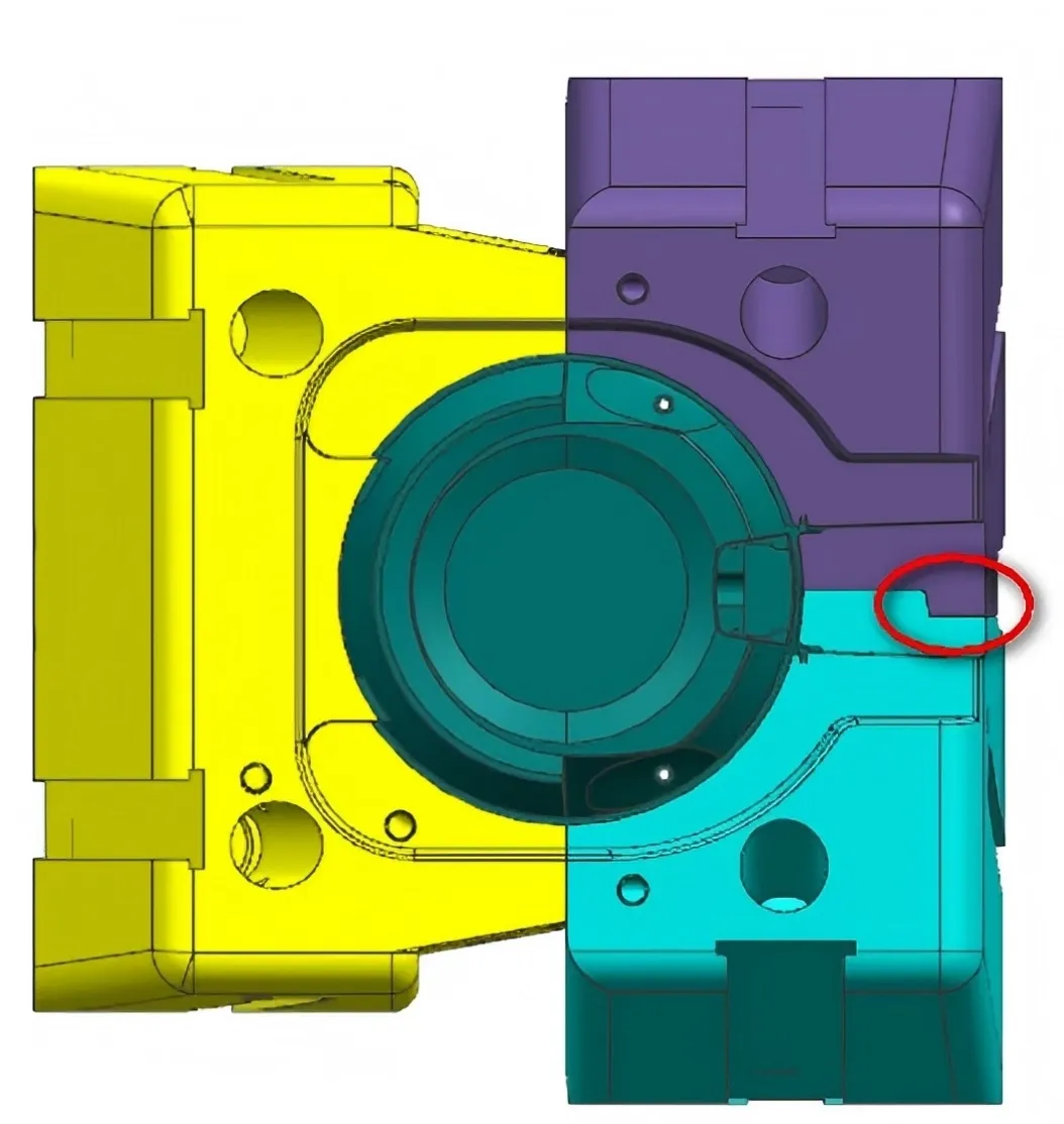
Mutual locking helps stabilize the slider interface and improve repeatable positioning under injection pressure.
Positive Pull-Back and 7-Shaped Hook Logic
Some front-mold half-slider designs use springs to initiate movement after the mold begins to open.
Springs can assist separation, but relying on spring force alone may not provide enough positive control for every application.
A mechanical pull-back feature, such as a 7-shaped hook or another positive-return mechanism, can be used to guide the slider back toward the intended open position during the mold-opening sequence.
This type of feature should be designed around the actual travel path and timing of the mechanism. It must provide enough clearance to avoid interference while maintaining reliable engagement throughout the required stroke.
Mechanical pull-back features can provide additional positive control and reduce reliance on springs alone.
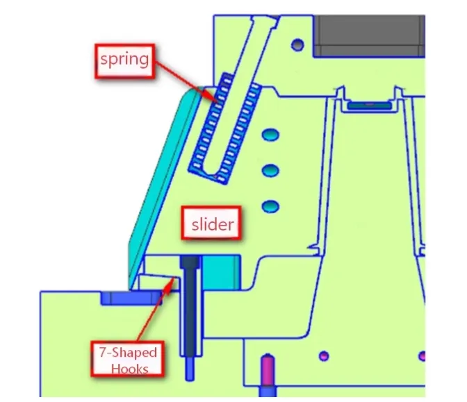
A positive pull-back feature can reduce dependence on spring force alone during slider retraction.
H2: T-Slot Guidance and Stroke Control
Reliable half-slider movement depends on controlled guidance.
T-shaped gibs, T-blocks or similar guide components can provide a defined sliding path and help the moving elements resist side loading during repeated production cycles.
The guide system should be evaluated for:
- alignment;
- bearing area;
- lubrication;
- wear;
- assembly access;
- replacement and maintenance.
For suitable high-cycle applications, self-lubricating wear components may be considered to reduce friction and simplify maintenance. The exact material and lubrication strategy should be selected according to the mold structure, production environment and expected tool life.
Dual-Side Stroke Limitation
The slider must also stop at a controlled position.
Limit blocks or other mechanical hard stops can prevent excessive travel that might overload angular pins, hooks, cooling connections or nearby components.
The stop position should be defined from the required undercut release distance rather than simply maximizing travel.
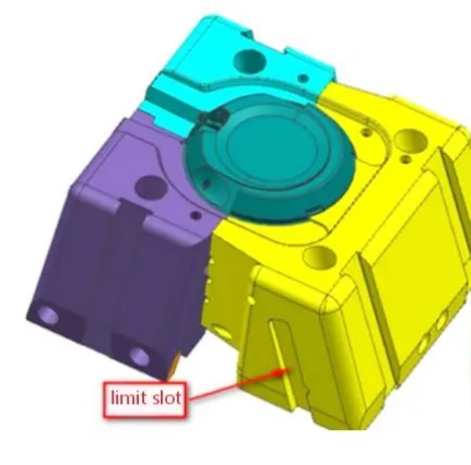
Mechanical stroke limits help control repeatable slider travel and protect surrounding mold components.
Mold Opening and Slider Sequencing
Motion sequence is one of the most important considerations in a complex half-slider mold.
The molded part, sliders and ejector system should never compete for the same space at the same time.
A typical sequence may be:
- The mold begins to open.
- Slider locking force is released.
- The side-action components begin moving away from the molded part.
- The required undercut clearance is achieved.
- Mold opening continues.
- The product remains on the intended mold half.
- Ejection begins after all relevant undercuts are safely released.
The exact sequence depends on the mold design, but one rule remains important:
Ejection should not begin while the molded feature is still mechanically engaged with the slider.
Premature movement can force the plastic part against the tooling and cause deformation, scratches, damaged ribs or excessive stress on the slider mechanism.
Coordination with the Ejection System
A successful slider design cannot be evaluated independently from the ejection system.
Once the side action has released the undercut, the molded part must remain sufficiently supported until the ejectors begin their movement.
Part Retention After Slider Release
The designer should confirm which mold half retains the molded component after the slider retracts.
If the slider releases a large cavity surface, the balance of adhesion can change significantly during mold opening.
Unexpected movement may result in unstable ejection or even cause the part to remain on the wrong side of the mold.
Ejector Placement
Ejector pins or other ejection components should act on regions capable of supporting the required demolding force.
Extra care is necessary around:
- thin walls;
- deep ribs;
- cosmetic surfaces;
- features close to the undercut;
- areas recently released by the slider.
Premature Ejection Risks
If ejection begins before sufficient slider clearance has been established, possible results include:
- distorted plastic features;
- drag marks;
- whitening or stress marks;
- broken ribs or hooks;
- damage to the slider or shut-off surfaces.
These conditions should be reviewed together with the overall ejection system design so that slider release and part ejection occur in the correct sequence.
Cooling Large Half-Slider Surfaces
When a half slider forms a large portion of the cavity surface, thermal balance can become part of the mechanism design.
Large moving inserts may accumulate heat, especially when they form thick sections or broad cosmetic surfaces. Uneven temperature can affect cooling time, dimensional stability and part consistency.
For sliders forming large cavity surfaces, dedicated internal cooling channels should therefore be evaluated where the available steel thickness, sealing requirements and connection layout permit.
The cooling design must also respect the slider movement. Water lines, fittings and hoses should not restrict travel or create collision risks during mold opening.
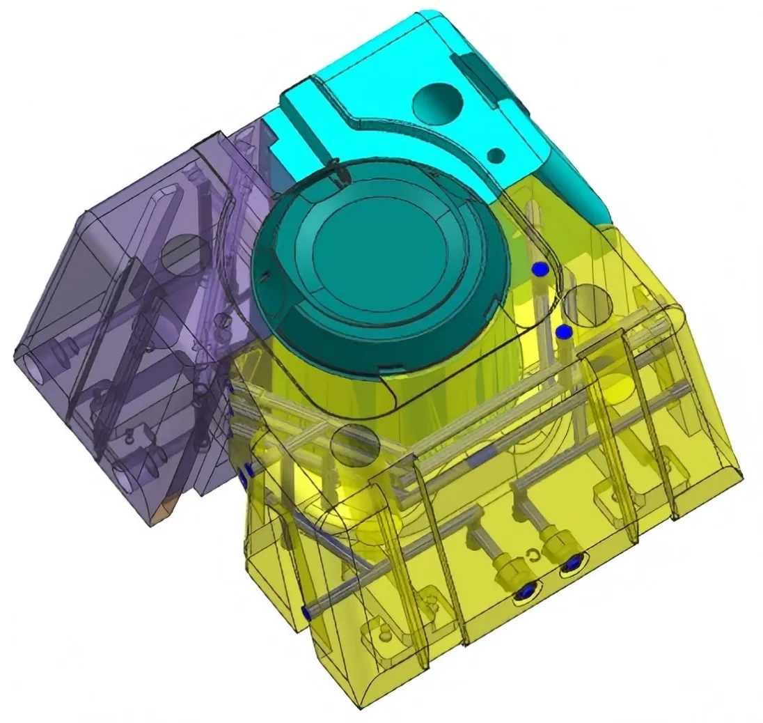
Dedicated cooling can be evaluated when a large half slider forms a significant portion of the cavity surface.
H2: Common Half-Slider Mold Design Problems
Manufacturing Accuracy Becomes More Critical as Slider Complexity Increases
As the number of moving components increases, dimensional accuracy and repeatability become more important.
A half-slider mechanism may include several interfaces that influence the final cavity position, such as:
- slider guide surfaces;
- locking blocks;
- wear plates;
- shut-off surfaces;
- cavity inserts;
- support components.
Small dimensional errors at each interface can accumulate and affect the final molding position.
For this reason, machining accuracy should not be evaluated only on individual components. The assembled mechanism must also be checked for alignment, contact condition and repeatable return position.
Machining and Fitting Accuracy
Critical slider and shut-off surfaces should be manufactured with sufficient accuracy to ensure stable movement and repeatable cavity positioning.
Depending on the mold structure, this may require:
- precision CNC machining;
- grinding;
- EDM;
- spotting and fitting;
- dimensional inspection;
- assembly verification.
The goal is not simply to achieve tight dimensions on every component, but to ensure that the complete mechanism functions as designed after assembly.
Wear and Long-Term Stability
A slider mechanism may work correctly during initial mold trials but gradually lose accuracy after repeated production cycles.
Wear can occur at:
- guide surfaces;
- locking faces;
- shut-off areas;
- wear plates;
- contact surfaces.
-
For long-production molds, the design should therefore consider replaceable wear components, lubrication access and maintenance procedures.
DFM Checks Before Finalizing a Half-Slider Mold
Half-slider mechanisms should ideally be evaluated during DFM and mold concept development rather than after the tooling structure has already been finalized.
A useful DFM review should consider both the plastic part geometry and the complete motion of the mold.
A 3D motion review is especially useful for complex molds because it allows the designer to evaluate the complete movement sequence before steel is cut.
This can help identify problems such as insufficient clearance, slider collision, weak shut-off conditions or difficult maintenance access before they become expensive tooling changes.
When a Simpler Mold Mechanism May Be Better
A half-slider mechanism is not automatically the best solution for every undercut.
More complex tooling usually means:
- more components;
- more machining;
- more fitting;
- higher maintenance requirements;
- more potential wear interfaces.
If the same molded geometry can be released reliably with a simpler mechanism, the simpler solution is often preferable.
Conventional Slider
A conventional slider is generally suitable when the undercut can be released in one clear lateral direction and sufficient mold space is available.
It is usually easier to manufacture, assemble and maintain than a split-slider system.
Lifter
A lifter may be appropriate for localized internal undercuts that can be released during the ejection stroke.
The mold designer must still consider lifter angle, travel, part retention and available ejector stroke.
Product Design Modification
Sometimes the most effective tooling solution is to modify the plastic part itself.
Possible design changes may include:
- reducing the undercut depth;
- changing the release direction;
- adding draft;
- moving a feature to the parting line;
- separating a complex feature into another component.
A small product-design change can sometimes eliminate an entire side-action mechanism.
This is one reason why DFM review before final mold design can reduce tooling complexity, cost and long-term maintenance risk.
Practical Engineering Checklist for Half-Slider Mold Design
Before releasing a half-slider mold design for manufacturing, verify the following:
- The undercut and release direction are clearly defined.
- Slider travel provides sufficient release clearance.
- The complete movement path has been checked for interference.
- Slider guidance and locking provide repeatable positioning.
- Shut-off surfaces have adequate support and sealing contact.
- Thin steel conditions have been avoided where possible.
- The slider is fully released before ejection begins.
- The molded part remains stable after slider retraction.
- Ejector locations do not deform weak or unsupported features.
- Wear surfaces and maintenance points are accessible.
- Cooling, screws and other components do not interfere with slider movement.
- The full mechanism has been verified in the assembled mold condition.
These checks are part of the broader injection mold design principles that connect product geometry, steel condition, cooling, ejection, machining and long-term mold stability.
Frequently Asked Questions
What is a half slider in injection mold design?
A half slider, or split-slider structure, uses two or more moving side-action components to form and release complex molded geometry. It is typically considered when a conventional single slider cannot provide the required release direction, clearance or cavity formation.
When should a half slider be used instead of a conventional slider?
A half-slider structure may be appropriate when a part has opposing undercuts, multiple release directions, limited space for a conventional slider, or geometry that requires the cavity to be divided between several moving components.
If a conventional slider can release the feature reliably, the simpler mechanism is generally easier to manufacture and maintain.
What is the difference between a mold slider and a lifter?
A slider typically moves laterally during mold opening to release an external or side undercut.
A lifter usually moves at an angle during the ejection stroke and is commonly used for localized internal undercuts.
The correct mechanism depends on the geometry, release direction, available stroke and mold structure.
How much travel does a mold slider need to release an undercut?
The slider must move far enough to completely clear the undercut plus an appropriate safety clearance.
The required distance depends on the actual geometry, slider angle, resin behavior, dimensional tolerance and the complete motion path. It should therefore be calculated from the 3D mold and part geometry rather than using one fixed universal value.
What causes flash around a slider shut-off surface?
Common causes include poor shut-off contact, slider misalignment, insufficient locking, worn sealing surfaces, inadequate support or dimensional variation in the slider mechanism.
The complete positioning and locking system should be checked rather than adjusting only the visible flash area.
Need a DFM Review for a Complex Undercut or Slider Mold?
Complex undercuts often require more than simply adding a side-action mechanism. Slider direction, travel, shut-off geometry, mold-opening sequence and ejection must be evaluated together to avoid interference, flash, premature wear and part deformation.
JST Mould supports DFM review, mold structure evaluation and production-ready tooling for complex injection-molded parts. If your component includes difficult undercuts, split sliders or multiple release directions, send us your STEP, IGES or other 3D CAD data for an engineering review.
Contact JST Mould to discuss your tooling project and DFM requirements.