
Sep 30, 2026Engineering Whitepapers
Injection Mold Lifter Design Guide: Angle, Travel, Stroke and Failure Prevention
A practical injection mold lifter design guide covering lifter vs slider, angle, travel, ejector stroke, guidance, wear, interference, timing, reset and common failure modes.
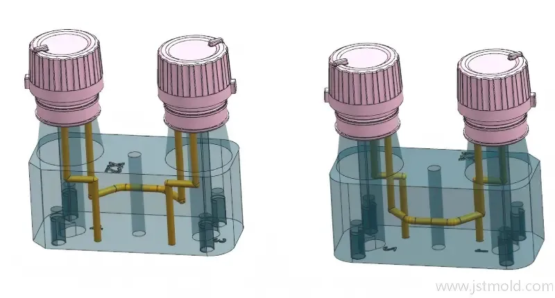
A lifter can be an efficient way to release an internal undercut, but it should not be treated as a simple angled ejector added at the end of mold design.
A reliable lifter has to work as part of the complete ejection system. Its release direction, angle, travel, ejector stroke, guidance, side load, wear, interference and reset sequence all affect whether the part can be ejected safely and whether the mechanism can survive long-term production.
At JST Mould, lifter design is therefore reviewed as a motion-control and DFM problem, not only as a question of choosing an angle.
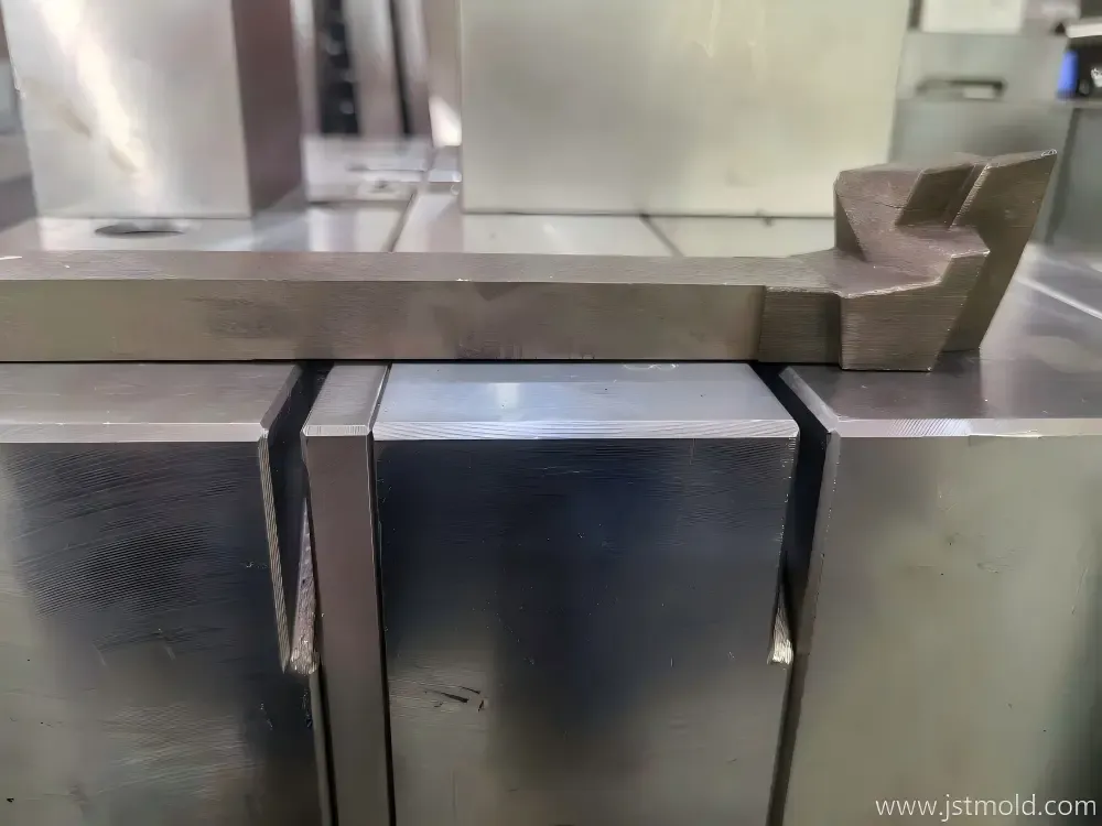
Real lifter manufactured for a recent JST mold project, showing the finished component used in an advanced undercut release application.
- What Is a Lifter in Injection Molding?
A lifter, also called an angled ejector, is a mold mechanism used mainly to release localized internal undercuts.
When the ejector system moves forward, the lifter travels upward together with the ejector plate while also moving sideways because of its inclined geometry. This combined movement allows the lifter head to clear the undercut before the molded part is fully removed from the core.
A lifter may also contribute to part ejection, but its primary function is not simply to push the part. Its key purpose is to generate controlled lateral release movement during the ejection sequence.
That is why the complete movement path must be checked from the fully closed position to full ejection and then back to the reset position.
2. Lifter vs Slider: Which Mechanism Should Be Used?
Lifters and sliders can both release undercuts, but they are not interchangeable.
A lifter is generally suitable when the undercut can be released during the normal ejection stroke and when the required lateral movement is moderate.
A slider is usually more appropriate when the side movement needs to occur independently from the ejector system, when the travel is larger, or when the undercut geometry requires stronger lateral support and more controlled movement.
A half slider or other special mechanism may be considered when the geometry is too complex for a conventional lifter or slider.
Decision table:
Design Question | Lifter | Slider |
|---|---|---|
Typical application | Local internal undercut | External or larger side undercut |
Driving movement | Ejector stroke | Mold opening / hydraulic / mechanical drive |
Lateral travel | Usually limited by ejector stroke and angle | Can be designed independently |
Timing | Linked to ejection | Can be controlled separately |
Space requirement | Often compact | Usually requires more side space |
Side load capacity | Must be carefully checked | Often better for larger side loads |
Maintenance | Simple when well guided | More components but independent movement |
3. Start with the Undercut: Calculate Required Release Travel First
One common mistake is to choose the lifter angle first and then try to make the rest of the system fit around it.
A better sequence is:
- Identify the actual undercut depth.
- Confirm the release direction.
- Determine the minimum lateral clearance needed for safe demolding.
- Check the available ejector stroke.
- Calculate whether the lifter can generate sufficient horizontal travel.
- Adjust the angle, stroke, product geometry or mechanism if necessary.
The basic geometric relationship is:
Horizontal lifter travel = vertical ejector stroke × tan(lifter angle)
This equation is useful, but it is only the starting point.
Actual release clearance may also be influenced by resin shrin
kage, product stiffness, draft, rib geometry, local deformation, assembly tolerance and the way the rest of the part remains on the core during ejection.
For this reason, JST does not recommend treating one fixed safety allowance as a universal rule for every lifter.
4. Choosing the Lifter Angle
The lifter angle directly affects both lateral travel and mechanical load.
If the angle is too small, the lifter may not generate enough horizontal movement within the available ejector stroke.
If the angle is increased, horizontal travel increases, but so do lateral force, friction, guide load and the risk of lifter bending or wear.
The final angle therefore needs to balance:
- Required undercut release distance
- Available ejector stroke
- Lifter length
- Lifter cross-section
- Guide condition
- Steel and surface treatment
- Expected production life
- Side load during ejection
There is no single “best” lifter angle that applies to every mold.
The correct angle is the one that produces enough release movement without creating unnecessary side load or mechanical risk.
5. Lifter Length, Cross-Section and Structural Strength
A long or slender lifter can become mechanically weak even if the release calculation looks correct.
The designer should check:
- Unsupported lifter length
- Minimum cross-section around the lifter head
- Changes in section thickness
- Stress concentration around shoulders or steps
- Side load generated during ejection
- Distance between the lifter head and guide position
If the lifter is too long or too thin, possible solutions may include adding guide support, shortening the unsupported section, increasing the cross-section, changing the mechanism, or splitting the function into another structure.
The goal is not only to make the lifter fit inside the mold. It must remain stable throughout repeated ejection cycles.
6. Guidance and Anti-Rotation
A lifter should be guided through its full working movement, not only positioned correctly when the mold is closed.
Depending on the structure, guidance may be provided by:
- Guide blocks
- T-slots
- Bottom support
- Additional support for long lifters
- Flat surfaces or keyed structures
- Anti-rotation features near the lifter head
Anti-rotation becomes especially important when the lifter head is asymmetric, when the molding surface must remain precisely aligned, or when rotation could cause interference with the product or neighboring mold components.
Good guidance reduces vibration, side movement and uneven wear.
7. Wear, Galling and Lubrication
Because the lifter moves at an angle, it is subjected to more side friction than a straight ejector pin.
Typical wear areas include:
- Lifter guide surfaces
- T-slot contact surfaces
- Base connection areas
- High-load side surfaces
- Shut-off surfaces near the lifter head
To reduce long-term wear, the designer may consider suitable steel combinations, hardness differences, surface treatments, replaceable wear components and lubrication features.
The exact material and hardness should be selected according to the mold life requirement, contact condition and production environment rather than treated as one universal standard.
For high-production molds, maintenance access should also be considered during the design stage.
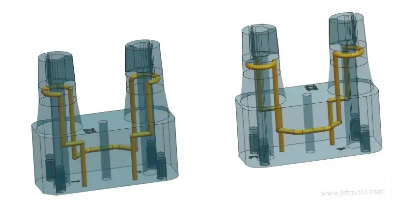
Transparent CAD view of an internally cooled lifter design used to improve thermal control in a complex mold structure.
8. Interference Check Through the Full Ejection Stroke
A lifter can be correct in the static mold assembly and still fail during movement.
For this reason, interference should be checked through the entire ejection stroke.
The lifter may interfere with:
- Product ribs
- Bosses
- Core inserts
- Ejector pins
- Ejector sleeves
- Neighboring lifters
- Water lines
- Screws
- Support pillars
- Ejector plates or guide components
The check should cover the complete path from mold-closed position to full ejection and then back to the reset position.
Dynamic motion review is more important than checking only the final position.
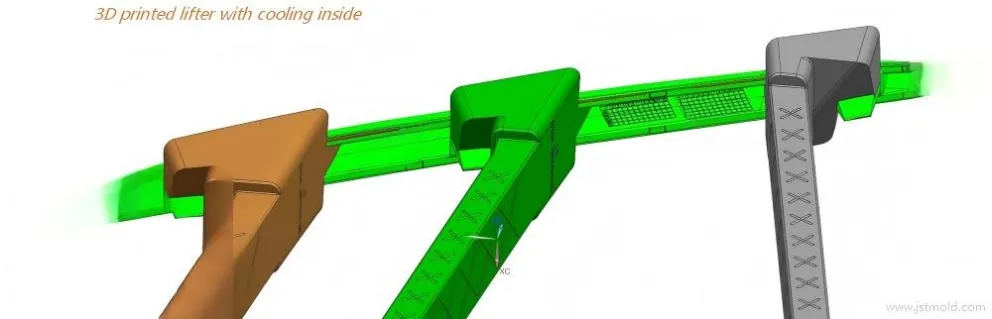
Engineering CAD view of a 3D-printed lifter concept with internal cooling integrated into the lifter body for a complex mold application.
A 3D-printed lifter with integrated internal cooling allows cooling paths to follow geometry that may be difficult to machine conventionally.
9. Ejection Timing and Reset Sequence
Lifter design must be checked as part of the full mold movement sequence.
A typical sequence is:
- The mold opens.
- The ejector system starts moving.
- The lifter moves upward and sideways.
- The undercut clears the molded part.
- The part completes ejection.
- The ejector system returns.
- The lifter returns to its molding position.
- The mold closes only after the lifter is safely reset.
Potential timing problems include:
- The lifter begins releasing while the part is still strongly retained elsewhere.
- The part starts moving before the undercut is fully cleared.
- The lifter interferes with an ejector pin or sleeve.
- A long lifter deflects during the stroke.
- The lifter does not fully reset before mold closing.
- A secondary ejection action starts too early or too late.
These problems may not be visible when reviewing only a single static CAD section.
10. Shut-Off, Parting and Flash Around the Lifter
The lifter head is also part of the molding surface.
Its shut-off and fitting surfaces must resist molding pressure while still allowing smooth movement during ejection.
Poor fitting or wear may lead to:
- Flash around the lifter
- Visible mismatch lines
- Local drag marks
- Uneven shut-off pressure
- Increasing maintenance frequency
Steel-safe adjustment is often useful where the local fit may need to be tuned after mold trial.
The designer should also consider how the lifter interface relates to the local parting and sealing structure.
11. Common Lifter Failure Modes and What They Usually Mean
Failure Mode | Typical Cause |
|---|---|
Undercut does not fully release | Horizontal travel too short / ejector stroke insufficient |
Lifter seizure or galling | Excessive side load / poor guidance / lubrication issue |
Lifter bending | Long unsupported section / weak cross-section / excessive lateral load |
Part drag mark | Undercut not fully cleared before part movement |
Part deformation | Incorrect release timing / part retained in another area |
Flash near lifter | Shut-off wear / poor fit / lifter movement under molding pressure |
Lifter head rotation | Insufficient anti-rotation control |
Collision during ejection | Incomplete dynamic interference check |
Collision during mold closing | Lifter or ejector system not fully reset |
A failure should therefore be traced back to motion, force, guidance, fit and timing rather than treated only as a lifter component problem.
12. DFM Checklist Before Releasing the Lifter Design
Before the lifter design is released for manufacturing, the following questions should be reviewed:
□ Is a lifter actually simpler and safer than a slider?
□ Is the true undercut release direction confirmed?
□ Is the required horizontal travel calculated?
□ Is the available ejector stroke sufficient?
□ Is the selected lifter angle mechanically reasonable?
□ Is the lifter cross-section strong enough for the expected side load?
□ Is the lifter guided through the complete working stroke?
□ Is anti-rotation required?
□ Have wear and lubrication been considered?
□ Has dynamic interference been checked through the full stroke?
□ Is the ejection timing safe?
□ Is reset positively controlled before mold closing?
□ Can the lifter be inspected and maintained without excessive mold disassembly?
This type of DFM review is especially important when multiple lifters, deep ribs, long ejector travel or complex internal undercuts are involved.
13. Advanced Lifter Design: Internal Cooling and Additive Manufacturing
Some lifters are large enough to form a significant area of the molded part or are located in regions where heat is difficult to remove.
In these cases, conventional straight drilled cooling may not provide adequate access to the critical area.
One option is to use additive manufacturing to create an internal cooling channel inside the lifter.
This does not mean that every lifter requires 3D printing.
The decision should depend on:
- Lifter geometry
- Available conventional machining access
- Local heat concentration
- Cooling distance to the molding surface
- Structural strength
- Internal channel reliability
- Cost and tool-life requirement
In a recent JST mold project, an internally cooled 3D-printed lifter was manufactured and delivered as part of the final tooling solution.
The design allowed the cooling path to follow the lifter geometry more closely than a simple straight drilled passage.
Complete project CAD view showing how the internally cooled lifter is integrated into the mold and part geometry.
14. When Moldflow Matters — and When It Does Not
Moldflow can support the design of an injection mold, but it does not replace mechanical verification of lifter movement.
Moldflow is more relevant when the lifter forms a large product surface, when cooling around the lifter is difficult, or when local temperature differences may contribute to shrinkage or warpage.
Mechanical questions such as:
- Does the lifter clear the undercut?
- Is the travel sufficient?
- Will the lifter collide with another component?
- Does it reset safely?
must still be verified by mold design and motion review.
15. Conclusion
Good lifter design is a motion-control problem, not simply an angle-selection problem.
The designer must connect the part undercut, required release travel, ejector stroke, lifter angle, structural strength, guidance, wear condition, interference, timing and reset sequence into one complete mechanism.
For simple undercuts, a conventional lifter may be the most efficient solution.
For larger movement, heavier side load or independent timing, a slider may be more appropriate.
For complex cases, special structures such as half sliders, guided lifters or internally cooled additive-manufactured lifters may be considered.
If your plastic part contains internal undercuts, JST Mould can review the release direction, lifter or slider concept, ejector stroke and interference risks during DFM before tooling manufacture.
Or