
Aug 25, 2026Precision Engineering & Tooling
Case Study: 33% Cycle‑Time Reduction via 3D‑Printed Conformal Cooling
Fighting hot-spots, sink marks & long molding cycles? Real-world conformal cooling 3D printed mold project cuts cycle time 33% for global injection-mold clients.
Executive Summary
When conventional straight drilled cooling lines cannot adequately cool complex core inserts, molding cycle times spike and scrap rates increase.
Not familiar with the core differences between conformal cooling and conventional drilled cooling? Please visit our Conformal Cooling vs Traditional Straight Cooling Lines Guide for full technical background.
This case study demonstrates how JST Mould deployed a conformal cooling 3D printed mold core insert for a consumer electronics USB upper cover, cutting cycle time from 30s to 20s (a 33.3% productivity boost) while achieving stable, defect‑free mass production[cite: 1]. We also highlight extended application cases across automotive optical, interior lifter, and medical deep‑cavity tooling.
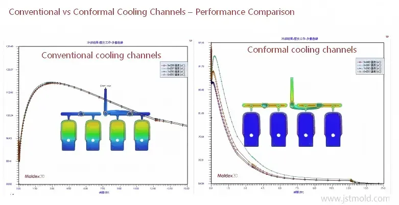
Figure 1: Moldex3D thermal analysis comparison showing how conformal cooling eliminates core heat accumulation and drastically accelerates heat dissipation.
- Primary Case: Consumer Electronics USB Cover Insert
Project Background & Mechanical Challenge
For this consumer electronics USB upper‑cover injection mold, original tooling arranged cooling lines only on the cavity (mother‑mold) side. The compact core insert contained zero internal cooling due to space constraints and ejector‑pin interferences.
(👉 Insert Image 2 here: Moldex3D simulation showing USB cover mold with cavity‑only cooling)
- Original Tooling: Cavity cooling only; severe core heat accumulation.
- Baseline Injection Cycle: 30.0 seconds.
- Mass‑Production Risk: Heat accumulation on the core led to part dragging, sink marks, and unstable dimensional Cpk values.
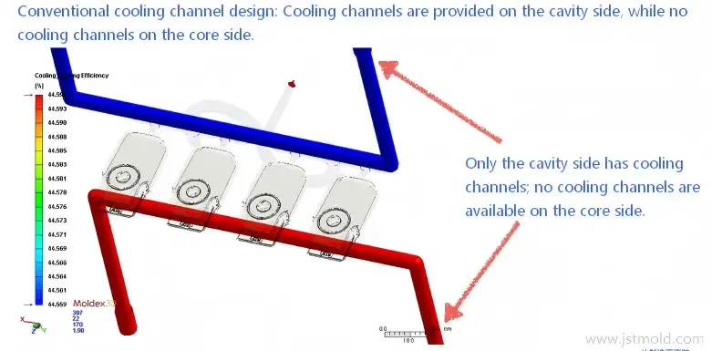
Figure 2: Initial Moldex3D layout demonstrating the original tooling limitation with cavity-only cooling, leaving the core insert completely uncooled.
The JST Mould Conformal Solution
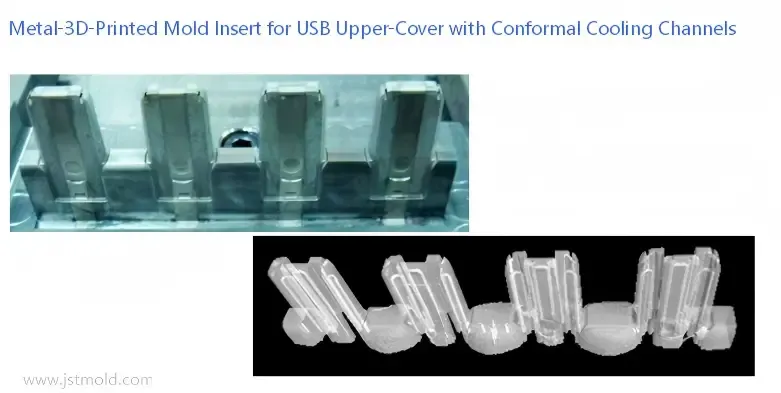
JST Mould engineered a fully integrated core insert manufactured via SLM metal 3D printing for mold applications using high‑hardness maraging tool steel (1.2709).
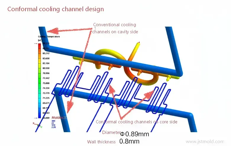
Figure 3: Optimized Moldex3D conformal channel design featuring Φ 0.89 mm micro-passages running 0.8 mm parallel to the core contour.
- Internal Passage Diameter: Φ 0.89 mm.
- Cavity Distance: 0.8 mm uniform wall proximity.
- Channel Profile: 3D spiral galleries fully contouring the high‑heat core surface.
Figure 4: Precision SLM metal 3D-printed 1.2709 tool steel core insert along with 3D internal imaging showing the conformal cooling network.
Shop‑Floor Performance Metrics Comparison
Performance Metric | Original Traditional Cooling | Metal 3D‑Printed Conformal Cooling | Engineering Outcome |
Core Cooling Layout | No core cooling[cite: 1] | Integrated conformal cooling mold insert[cite: 1] | Complete core thermal coverage[cite: 1] |
Injection Cycle Time | 30.0 s[cite: 1] | 20.0 s[cite: 1] | 33.3% cycle‑time reduction[cite: 1] |
Hourly Output / Cavity | Baseline (100%) | 150% Capacity | 50% throughput expansion[cite: 1] |
Core Temp Delta | Severe core hot spots[cite: 1] | Uniform temperature profile[cite: 1] | Hot spots fully eliminated[cite: 1] |
Part Quality & Yield | High sink‑mark risk[cite: 1] | Tight tolerances, zero warpage[cite: 1] | Yield rate increased to >95%[cite: 1] |
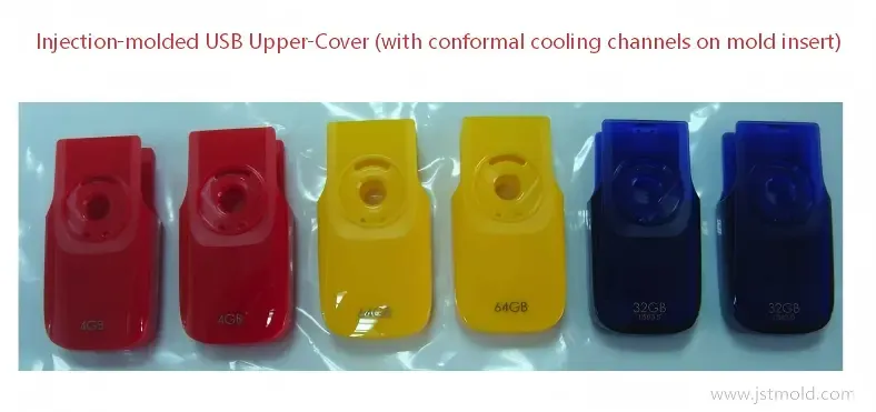
Figure 5: Mass-produced USB upper cover parts featuring defect-free surface finish and tight tolerances achieved under a 20-second cycle time.
- Extended Industry Applications: Automotive & Medical Tooling
Beyond consumer electronics, JST Mould applies automotive mold conformal cooling and precision medical tooling solutions across complex overseas projects:
Case A: Automotive Optical Lens & Light Guide Molds
- The Challenge: Thick‑walled PC/PMMA optical components cool extremely slowly and easily develop internal vacuum bubbles, sink marks, and optical yellowing.
- Conformal Solution: 3D spiral conformal channels wrapping around thick‑walled lens sections.
- Result: Reduced cooling time by 40%, eliminated internal thermal stress, and achieved OEM optical clarity standards.
Case B: Automotive Door Trim 3D Printed Lifter with Conformal Cooling Inserts
- The Challenge: Narrow door trim lifters operate in deep cavities where straight drilling is impossible, causing lifter overheating, galling, and part scuff marks.
- Conformal Solution: One‑piece SLM printed lifters featuring embedded micro‑cooling loops.
- Result: Eliminated localized lifter heat traps, smoothed mold ejection, and prevented part dragging during continuous mass production.
Case C: Medical Deep‑Cavity Pipette & Tube Molds
- The Challenge: Long, slender core pins (high length‑to‑diameter ratio) suffer from poor baffle pipe cooling, resulting in part eccentricity and warpage.
- Conformal Solution: Dual‑interlocking spiral conformal passages printed directly inside 6 mm diameter core pins.
- Result: Compressed molding cycle from 18s to 11s while maintaining strict medical‑grade concentricity tolerances (±0.005 mm).
Engineering Note: All conformal cooling layouts are validated via Moldex3D simulation to balance flow velocity, pressure drop and mold structural integrity before metal printing.
- Project‑Focused FAQ
Full technical FAQs regarding material properties and channel mechanics can be found in our Conformal Cooling vs Traditional Straight Cooling Lines Guide.
Q1: Does a 3D‑printed conformal insert require higher initial project investment?
While SLM additive manufacturing adds upfront insert costs, the 33%+ cycle‑time reduction and lower scrap rates recover the investment within the initial mass‑production runs. We provide transparent ROI calculations for your project prior to tooling.
Q2: Can I retrofit a conformal cooling mold insert into an existing mold base?
Yes. Full mold rebuilding is unnecessary. Replacing only the problematic core inserts, cavity blocks, or a 3D printed lifter with conformal cooling delivers immediate cycle‑time savings at minimal modification cost.
💬 Request Your Custom Cooling Optimization Proposal
Struggling with long cycle times, thermal warpage, or overheated lifters on your export molds? Submit your 3D CAD files today and receive:
✅ Free DFM & Conformal Cooling Feasibility Assessment
✅ Moldflow Thermal Simulation & Channel Layout Analysis
✅ Production ROI & Payback Calculation
📩 Contact JST Mould Engineering Team:
Facility Location: Shenzhen, Guangdong, China