
Sep 15, 2026Tier-1 Success Stories
Precision Plastic Gear Molding | POM Gear Tooling & Real Samples
See real precision plastic gear samples from JST Mould and learn the key tooling factors behind POM gear molding, tooth accuracy, dimensional stability and reliable production.
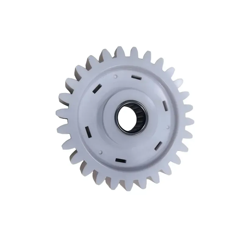
Precision plastic gears may look simple, but their performance depends on much more than reproducing a basic tooth shape.
Tooth geometry, concentricity, polymer shrinkage, warpage, gating, cooling and dimensional consistency can all affect how a molded gear performs after assembly.
At JST Mould, we have practical experience supporting precision plastic gear tooling and molded transmission component programs. The gear parts shown on this page are real molded samples retained in our in-house sample collection from completed manufacturing programs.
Many of these gear components are made from POM, a material widely used for molded transmission parts because of its low friction, wear resistance and dimensional stability.
For buyers developing a new plastic gear, however, material selection is only one part of the engineering challenge. Reliable production begins with the interaction between part design, mold accuracy, polymer behavior and process control.
Real Precision Plastic Gear Samples from JST Mould
Real precision plastic gear sample retained in JST Mould's in-house sample collection.
The samples shown here are not stock images or conceptual renderings. They are physical molded parts retained from previous manufacturing programs.
They demonstrate JST's practical experience with molded gear geometry and precision transmission components.
Depending on the application, a plastic gear may include fine tooth profiles, a central hub or bore, stepped geometry, mating features, reinforcing structures or other functional details that must remain stable after molding.
For a precision gear, appearance alone is not enough. A part can look visually acceptable while still failing to mesh correctly, rotate smoothly or maintain the required relationship with another component.
That is why tooling accuracy and dimensional control need to be considered from the beginning.
Why Precision Plastic Gears Are Difficult to Injection Mold
Tooth Geometry Must Be Reproduced Consistently
Gear teeth contain repeated fine features around the full circumference of the part.
Any local variation caused by filling behavior, shrinkage or mold accuracy can influence how the gear engages with its mating component.
For this reason, cavity machining accuracy and stable molding conditions are especially important for gear components.
Shrinkage Can Affect More Than the Overall Diameter
Engineering plastics shrink as they cool, but the effect is not always uniform across the part.
In a molded gear, engineers may need to consider the relationship between tooth geometry, hub thickness, wall thickness variation, gate location, cooling balance and material flow direction.
If these factors are not properly considered, dimensional changes can occur between the outer gear teeth and the central bore or hub.
Concentricity and Runout Matter in Functional Assemblies
For many transmission applications, the relationship between the gear teeth and the center bore is critical.
If the molded gear is not sufficiently concentric, the gear may rotate unevenly or produce inconsistent contact with the mating component.
The required tolerance depends on the application, engineering drawing and functional requirement.
JST does not assume one universal tolerance for every plastic gear. Critical dimensions should be reviewed according to the customer's actual assembly and performance requirements.
Warpage Can Change Gear Performance
A molded gear must remain sufficiently flat and stable after cooling.
Uneven cooling, asymmetric geometry, material orientation or inappropriate process conditions can contribute to warpage.
Even when the tooth profile is molded correctly, overall distortion may still affect assembly or rotation.
This is why cooling design and process stability are part of precision gear tooling, not secondary considerations.
Key Tooling Factors for Precision Plastic Gears
A precision plastic gear mold should be developed around the functional requirements of the component rather than only its external shape. For projects involving high-precision injection tooling, JST reviews how mold design, machining accuracy, material behavior and process stability work together.
Mold Insert Accuracy
The cavity and core forming the gear must reproduce repeated tooth geometry accurately and consistently.
Machining strategy becomes especially important where the gear includes fine teeth, small radii, narrow grooves or a closely controlled central feature.
For precision tooling, JST evaluates the relationship between mold design, CNC machining, EDM where required, fitting and final mold assembly.
Shrinkage Compensation
Plastic gear dimensions cannot simply be copied directly from the finished-part drawing into the mold.
Material shrinkage, local geometry and process behavior need to be considered during tooling development.
For materials such as POM, the expected molding behavior should be reviewed together with the customer's critical dimensions and mating requirements.
The goal is not only to reach nominal dimensions at the first trial, but to create a mold that can be adjusted and validated efficiently when necessary.
Gating and Filling Balance
Gate position affects how molten plastic enters and fills the cavity.
For gear parts, poor filling balance may contribute to uneven packing, local shrinkage or distortion.
The appropriate gate design depends on the gear geometry, material, cavity layout, cosmetic requirements and production volume.
There is no single gate solution that is correct for every precision plastic gear.
Cooling Design
Balanced cooling supports dimensional repeatability.
Areas with different wall thicknesses can cool at different rates, especially around hubs, ribs and thicker central sections.
During mold design, cooling should therefore be considered together with geometry rather than added as an afterthought.
Venting and Ejection
Fine gear features also require careful venting so trapped gas does not interfere with complete cavity filling.
At the same time, the ejection system should remove the molded part without damaging the teeth or creating unnecessary deformation.
The appropriate ejection method depends on the part geometry and the functional surfaces that must be protected.
Why POM Is Commonly Used for Molded Plastic Gears?
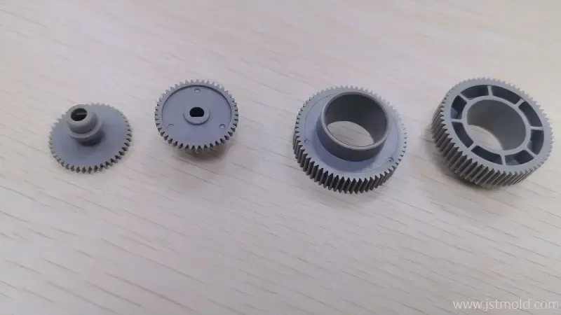
Real molded gear and transmission component samples retained in JST Mould's sample collection.
POM, also known as acetal, is commonly used in molded gears and transmission components.
Its popularity comes from a combination of properties that can be useful in moving assemblies, including relatively low friction, good wear resistance, good stiffness, dimensional stability and good fatigue performance.
However, selecting POM does not automatically make a gear precise.
The final dimensional result still depends on part design, mold accuracy, material behavior, molding process and inspection.
Other engineering plastics may also be suitable depending on temperature, load, chemical exposure, noise, lubrication and cost requirements.
Material selection should therefore be reviewed according to the actual application rather than based only on a general recommendation.
What Real Gear Samples Can Tell You — and What They Cannot
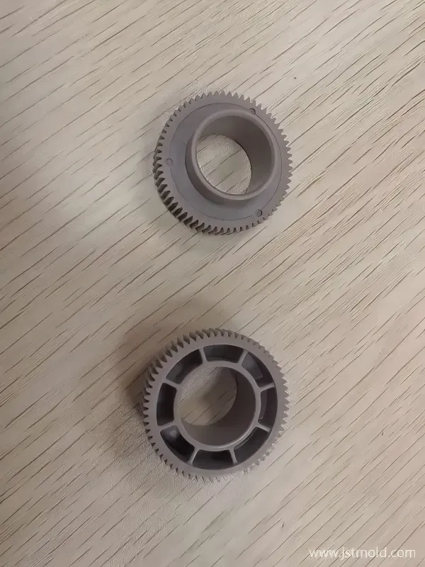
Real molded plastic gear samples showing different hub and tooth geometries.
Physical samples are useful because they show actual manufacturing experience.
From a real molded part, a buyer can evaluate visible features such as tooth definition, molded surface quality, hub geometry, structural complexity, parting line location and general molding consistency.
However, a photograph alone cannot prove that a gear meets a specific dimensional tolerance or functional requirement.
That requires appropriate verification against the engineering drawing and application.
Depending on the project, validation may include dimensional inspection, bore and diameter measurement, concentricity or runout checks, mating tests, assembly evaluation and functional testing.
A good-looking gear is not automatically a high-precision gear. Precision must ultimately be confirmed by measurement and function.
Complex Molded Gear and Transmission Geometry
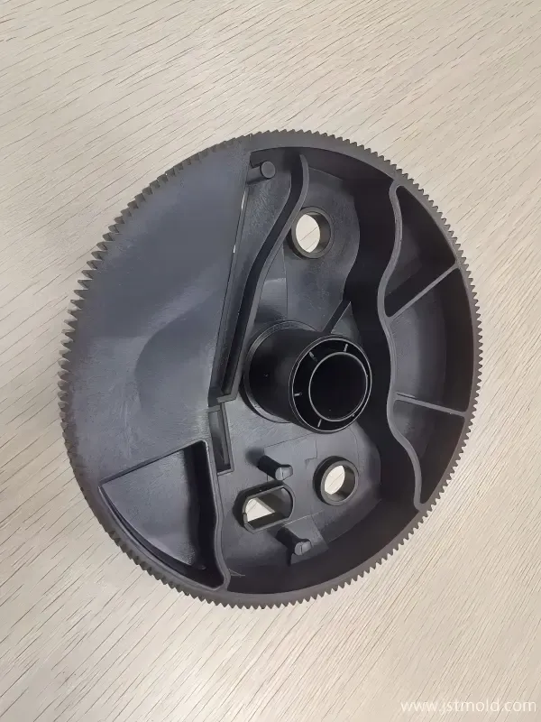
Real complex molded gear and transmission component sample from JST Mould.
Not every molded gear is a simple standalone wheel.
Some transmission components combine gear teeth with hubs, support structures, mounting features or other molded functions in one part.
These designs can introduce additional tooling considerations because dimensional control is required across both the gear features and the integrated structure.
For buyers, this is another reason to review the complete assembly and mating conditions rather than evaluating the gear tooth profile alone.
What JST Reviews Before Quoting a Precision Plastic Gear Project
The more complete the technical information, the more accurately a gear mold can be evaluated before quotation.
For a new project, buyers should ideally provide:
- 3D CAD data
- 2D engineering drawing
- plastic material or material requirement
- gear module and tooth information, if applicable
- mating component information
- critical dimensions and tolerances
- annual or lifetime production volume
- expected mold life
- application environment
- inspection requirements
If a complete drawing is not yet available, an existing physical sample may also help with an initial engineering discussion.
For projects based on an existing molded part, JST can review the available sample and technical information before determining the appropriate next step.
From Gear Sample to Production Tooling
A precision gear project usually requires coordination across several engineering stages. A typical JST workflow may include DFM review, mold design, tooling manufacture, mold assembly, mold trial and dimensional verification, optimization and production readiness.
The exact process depends on the application and customer requirements.
For gear components, JST pays particular attention to how mold design and molding conditions influence the functional relationship between the tooth profile, center feature and overall part geometry.
See Our Precision Plastic Gear Components
For a closer look at our precision plastic gear components and related manufacturing capability, visit our dedicated product page.
That product page is intended for buyers who want a quick capability overview, while this article explains the engineering considerations behind precision molded gear programs.
Why Buyers Choose an Experienced Tooling Partner for Plastic Gears
Precision gears are a good example of why plastic injection molding should not be evaluated only by part appearance.
A supplier needs to understand how mold construction, machining accuracy, polymer shrinkage and process stability interact.
When the application is sensitive to dimensional variation, early engineering review can reduce unnecessary mold modifications and make validation more efficient.
JST Mould supports customers with precision injection tooling, mold manufacturing, trial support and molded-part verification for technically demanding plastic components.
For projects involving critical dimensions, complex geometry or transmission functions, our team can review the drawing before quotation and identify the main tooling considerations.
FAQ
Can plastic gears be manufactured by injection molding?
Yes. Injection molding is widely used for plastic gears when the geometry, material, mold design and production process are properly controlled. It is especially suitable for repeat production once the tooling has been validated.
Why is POM commonly used for molded plastic gears?
POM offers a useful combination of low friction, wear resistance, stiffness and dimensional stability, making it suitable for many moving and transmission components. The final material choice should still be based on the actual load, temperature, mating components and application environment.
What affects the accuracy of an injection molded plastic gear?
Key factors include mold machining accuracy, polymer shrinkage, gate location, filling balance, cooling, part geometry and molding process stability. Final gear accuracy should be verified against the customer's drawing and functional requirements.
Can JST quote a plastic gear mold from an existing sample?
An existing physical sample can be useful for an initial review, but complete 3D data and a 2D drawing are normally preferred for accurate mold quotation and tolerance evaluation. If only a sample is available, JST can first review the available information and discuss the next engineering step.
What information should I provide for a precision plastic gear mold quotation?
Ideally, provide 3D CAD, a 2D drawing, material specification, critical tolerances, annual volume, application requirements and any relevant mating-part information. These details help the tooling team evaluate the project more accurately.
Need a Mold for a Precision Plastic Gear?
Send us your 3D CAD, 2D drawing, material requirement and expected production volume.
If you already have an existing gear sample, you can also tell us what needs to be improved — such as dimensional stability, tooth accuracy, assembly fit or molding consistency.
Our tooling team can review your part and provide an initial engineering assessment covering:
- mold feasibility
- material and shrinkage considerations
- critical dimensions and tolerance risks
- tooling strategy
- trial and validation requirements
You do not need to prepare a complete technical package before contacting us. If some information is still missing, send what you already have and we can review the next step with you.